 |
|
|
| Site Navigation
Projects & Information
»General Information»Wind turbine Projects »The F&P Smartdrive »Electronic projects »Microcontroller projects »Miscellaneous Kits & Parts
»Basicly Natural Pty Ltd»PVC & Aluminium blades »Scale model farm windmills »Price Watch Discussion Forums
Handy Links
»Wind»Solar »Electric Vehicles »Electronics »Micro Controllers »General Interrest About TheBackShed Getting Started Privacy Policy |
Converting a cheap sensor light to 12 volts.
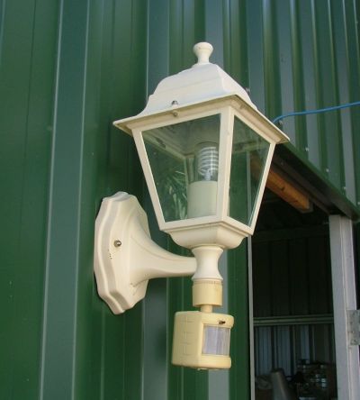
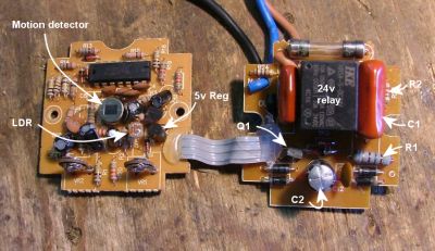
As part of my project of converting the workshop lights to 12 volts, I wanted to add a security/sensor light near the main doorway that would run of 12 volts. You can buy 12 volt PIR sensors, but these are very expensive at over $50 each and designed for security systems. However you can pick up a 240v sensor light for less than $20 from any hardware store, so I wondered if one of these could be converted to 12v operation. I already had this sensor lamp, so it was the guinea pig. Once I opened the sensor case ( after I of course disconnected the lamp from the mains power ), and accidentally broke off the small adjustment knobs, I found the sensor consisted of two circuit boards. Shown in the picture below (remember you can click on most pictures to see a larger image ), the left circuit board is the sensor, and the right circuit is power and relay driver. There is also a LDR ( Light Dependent Resistor ) there, this is used to stop the lamp turning on during the day. When you test your sensor light, remember to cover this with black tape to block out the light. Another thing to remember when you want to test you sensor, is the PIR will only work with the frenzel lens in place. |
This is the circuit diagram of the parts of interest for our conversion.
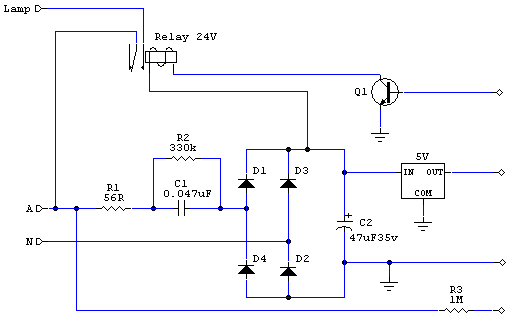
This is a generic circuit for these sensor lamps, the component values may vary from model to model. R1 is a fusible resistor, so it acts as a fuse as well as a dropping resistor. C1 and R2 are the main voltage dropping components. Diodes D1 to D4 make a bridge rectifier, fed into C2, our main filtering cap, and then a 5 volt regulator, to supply 5 volts to the sensor circuit. In some models I've see zener diodes used in the bridge rectifier, or across the output, to keep the voltage below 30 volts. This protects the 5v regulator from excessive input voltage.
Transistor Q1 receives it drive from the sensor circuit, and switches a 24v relay, turning on the lamp when the unit detects motion. Resistor R3 is the mains power sense input to the sensor circuit, and this can be a little tricky. Basically when the mains power is switched off and on quickly, the circuit switches the lamp on, and keeps it on, until the power is turned off for 10 or more seconds. The idea is you can flick you light switch to make the sensor lights stay on, but as everyone knows, it also means the sensor lights come on and stay on after a dip in the mains power, which is a real pain in the bum.
Converting to 12v
Most of the circuit runs at 5 volts, so it should be a straight forward process to convert these lamps to 12v operation, but there are a few little problems we need to sort out.
This circuit is a conversion from 240 to 12v.
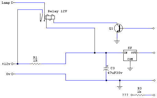
You can see I've removed the voltage drop components and the bridge rectifier. You could leave the bridge rectifier there as a safety measure in case you swap the +ve and -ve connectors, but remember this introduces a voltage drop of about 1.2 volts. I've also replaced R1 with a 1R fusible resistor. Or I could have just used a fuse, the circuit board above is a good model and has a fuse already on the circuit board.
My power supply will be 12v, so I need to replace the 24v relay with a 12v relay. However, if you wanted to run this circuit from a 24v source you could leave the 24v replay in place.
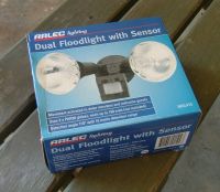
R3, the little bugger! A few years ago I converted one of these sensor lights to 12v operation as part of a burglar alarm for my car, and I remember I needed to connect this mains sense input to +12v to make the circuit work properly. So this time I went out and bought a Arlec sensor light from Dick Smith for $19, and tried the same connection for the mains sense input. Didn't work, in fact I could not get the thing to work reliable at all. I found this sense wire on this model needs to see AC to work properly, if I connected it to ground or power it would not work, if I let the input float free, it would pick up enough AC hum in the air to work, most of the time! I even tried a length of wire on this input to act as a aerial, still no reliable operation, so I gave up. There is nothing wrong with this unit for its intended 240v operation, but its not suitable for conversion to 12v.
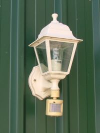
However this model below worked great. It didn't have a mains sense input at all, making my life much easier. If your going to buy a sensor light just for conversion to 12v, see if you can get one without the "Manual Override" feature.
So for R3, you would need to experiment. Drop the resistor value to something like 1k, and then try it on 0, 5v, and 12v to see if you can trick the circuit into working.
Once I had the sensor working, I needed a 12v bulb. I found this at my local light supplier, it a 12v fluoro.
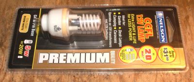
It works ok, but is a little dull. So I'll see what else I can fit in there that gives more light. The little relay I used has contacts rated at 3 amps, so this means I cant use a lamp over ( 3A * 12V ) 36 watts. But I could add a spotlight relay to drive some serious spotlights. The transistor Q1 wont have enough capacity to drive a spotlight relay, so I would use the existing relay to drive the bigger relay, or replace Q1 with a power Mosfet.
