
|
|
Forum Index : Solar : Solar Cell "internal" wiring
| Author | Message | ||||
| stef123 Senior Member Joined: 25/09/2024 Location: United KingdomPosts: 105 |
Hi, I have a "400-watt" solar panel from Dokio, which I’m not entirely satisfied with. The panel only begins to produce a reasonable amount of power when it is fully illuminated by the sun. By “insufficient power,” I mean that the panel produces only about 50 to 60 watts, even when approximately 90% of its surface is exposed to sunlight. It’s only when the remaining 10% is also fully illuminated that the output gradually increases -eventually reaching up to around 290 watts. This behavior results in a significant loss of potential energy yield, as the panel underperforms unless it receives nearly perfect sunlight coverage. Flipping the panel 180 degrees to “reverse” the current flow makes no difference. I understand that solar panels generally don’t perform well when partially shaded. However, in this particular case, I’m wondering whether it’s possible to modify the panel into two separate 200-watt sections. My idea is to modify (or possibly remove) what I assume is a bypass diode located on the back, in the middle of the panel. The goal would be to create separate positive and negative terminals—one for each half of the panel—in addition to the existing terminals located at the top and bottom. My Deye inverter has separate MPPT inputs for two panels, so this setup could potentially allow each half to operate independently. Of course, I’d then need to consider whether the voltage from each "half-panel" would be sufficient to trigger and operate the inverter’s MPPT tracking reliably. The panel is rated at around 31 volts and 13 amps under load, with an open-circuit voltage of roughly 37 volts and slightly higher current. Any modification would require careful assessment of whether the inverter’s MPPT can handle the new configuration. https://youtube.com/shorts/pYssSwMUfAk For context, I’m aware that the balcony’s handrail might cast a shadow, but that influence is minimal. The issue persists even when no shading is present at all in this area. What confuses me is the way the panel's surface is wired. In the center —where there are cutouts— there appears to be a diode at least in the middle (or possibly more), and both the positive and negative terminals are located in that central area. Additionally, there are visible interruptions in the wiring on both sides of the panel, though they are offset relative to the central cutouts. To be honest, I find the behavior of this panel quite odd. As I mentioned, I understand that partial shading can cause one string of cells to draw current and reduce the output of the entire panel. However, I don't understand why a relatively small unilluminated area causes such a significant drop in power output. I would have expected that the internal bypass diodes—in addition to the one located in the center—would mitigate this behavior and allow the rest of the panel to continue functioning more efficiently. Any ideas and explanations are very welcome ! Thanks! Stef Edited 2025-06-17 20:04 by stef123 |
||||
Revlac Guru Joined: 31/12/2016 Location: AustraliaPosts: 1277 |
Just had a quick look at the video, and I'm sure that there is too much shading on the panel, (there is shadow below the railing) to get close to its rated output, seldom get full output anyway. If you were looking at the same point of view that the sun is hitting the solar panel you couldn't see the entire panel, so the sunlight cant get to it either......Explanation might sound a bit simple.  To prove if the panel is working properly, it could be checked laying flat on the ground in full sunlight, that might not be possible in your location? Removing diodes and bypassing a row of cells will lower the overall voltage output of the panel......unless its a split panel as yours might be, then you could bypass that section, depends on which direction its split. likely shading is still a problem in that orientation, and I don't think you will gain anymore useful power, have you got a data sheet for that panel? that would help with the panel configuration. Cheers Aaron Off The Grid |
||||
| stef123 Senior Member Joined: 25/09/2024 Location: United KingdomPosts: 105 |
As I've found out, it seems to be a panel with a "triple" configuration — meaning I'm dealing with three cell sections in one panel. Its integrated (three) diodes should — at least in theory— bypass the sections or block current flow back to the cell sections which are partially or fully shaded, which is different from smaller panels without diodes at all. So, I suspect that one of the diodes is not working properly and one of the sections is dissipating a significant amount of current, or one of the sections is not properly put together - would not be the first time, i've got smaller Panels from other manufacturers which were, albeit on the first view perfectly fine, internally totally messed up - for example, the positive side of one cell row was connected to the first cells positive side of next row aswell, instead of going underneath it on order to create a single cell String, because the connecting terminals were on the same side - and produced nearly no Power/Current with strong voltage drops below 12 Volts under load conditions. If 90% of my Panel is exposed to strong sunlight, an output of 50 to 60 Watts output is far too low, especially given its internal configuration. I would understand such a drop if we were dealing with a single cell, with no diodes except those for the string configuration and bypassing an entire panel, and if some parts of the cell were shaded. The panel -does- get full sun exposure over its entire surface as the day progresses, but I barely get 0.6 kWh out of it per day, with at least 8 hours of being partially and fully exposed in those days, with a perfect and unblocked view to the sun and no clouds being visible. That's very low for a panel rated at (corrected) 410 watts, even considering that solar irradiance drops after midday and that 410 watts is typically only achievable in lab conditions. Edited 2025-06-18 13:18 by stef123 |
||||
| Revlac Guru Joined: 31/12/2016 Location: AustraliaPosts: 1277 |
Ok then, check each section with a meter while in full sunlight and see if anything isn't right, diodes etc, testing each section under some load should be helpful, I have found a few faulty panels but they were all old, some look good when reading short circuit current but didn't put out any useful power at VMP, thought that was a bit strange, haven't got around to fixing yet.  Just for an example using an old panel, 250w 60 cell open circuit voltage 38v, well it used to be.....not very sunny today so panel voltage is 35v total, this panel output will stop completely if any portion of it is shaded, and would be useless on its own, if it were in a string the rest of the panels should still work through the bypass diodes........I normally don't bother with any of this detail just connect a string of 3 for the MPPT charge controller and power on......lets go.....  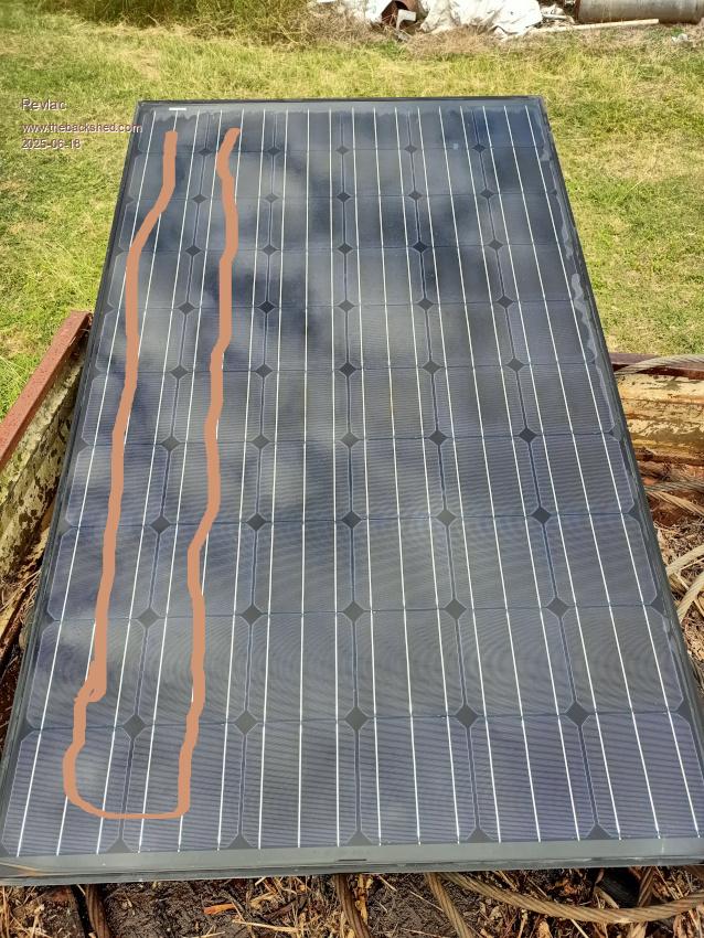 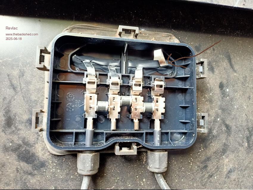 Now disconnecting one section (see line drawn on lower panel string) in the junction box and left the diode in place, the panel will now output 23.2v and the other section is 11.6, now we can shade the lower section and it has no affect on the rest of the panel, there is normally no reason to do this (just a demonstration) but I can use this to charge a 12v battery with an appropriate charge controller A little info on the diodes and how they are used..https://sinovoltaics.com/learning-center/off-grid/blocking-diode-bypass-diode-solar-panels/ you may have seen this already but if you haven't or it might be useful for someone else.  Cheers Aaron Off The Grid |
||||
| The Back Shed's forum code is written, and hosted, in Australia. | © JAQ Software 2026 |
