| Author |
Message |
Solar Mike
Guru

Joined: 08/02/2015
Location: New ZealandPosts: 1254 |
| Posted: 10:01am 30 May 2026 |
 Copy link to clipboard Copy link to clipboard |
 Print this post |
|
Though some members may be interested in this project; I'm building a PV powered resistive IR heating panel. Currently we have some unused PV panels sitting above an old chicken coup, 6 x 285w panels, 2 sets of 3 in series, mppt voltage is 93v at 18 amps. Short distance away is our office\reception in a 12m steel container, it gets quite cold in there first thing in the morning, even if its sunny; as the PV array gets sun from sunrise to after midday, perhaps we could utilize that energy to heat an alloy black painted sheet with 100 watt power resistors bolted to its back.
30 of these 100w, 150 ohm in parallel (5r) in full sun will each get 57w, may spread them over two blackened sheets each 60 x 120cm, 15 on each to make it easier to mount. Envisaged some simple box arrangement with the heating panel then fiberglass insulation, mounted facing down from the ceiling, panel temperature to be approx 100°C, this will warm up anyone sitting below. I don't expect full output power in winter, but any sun will provide some heating.
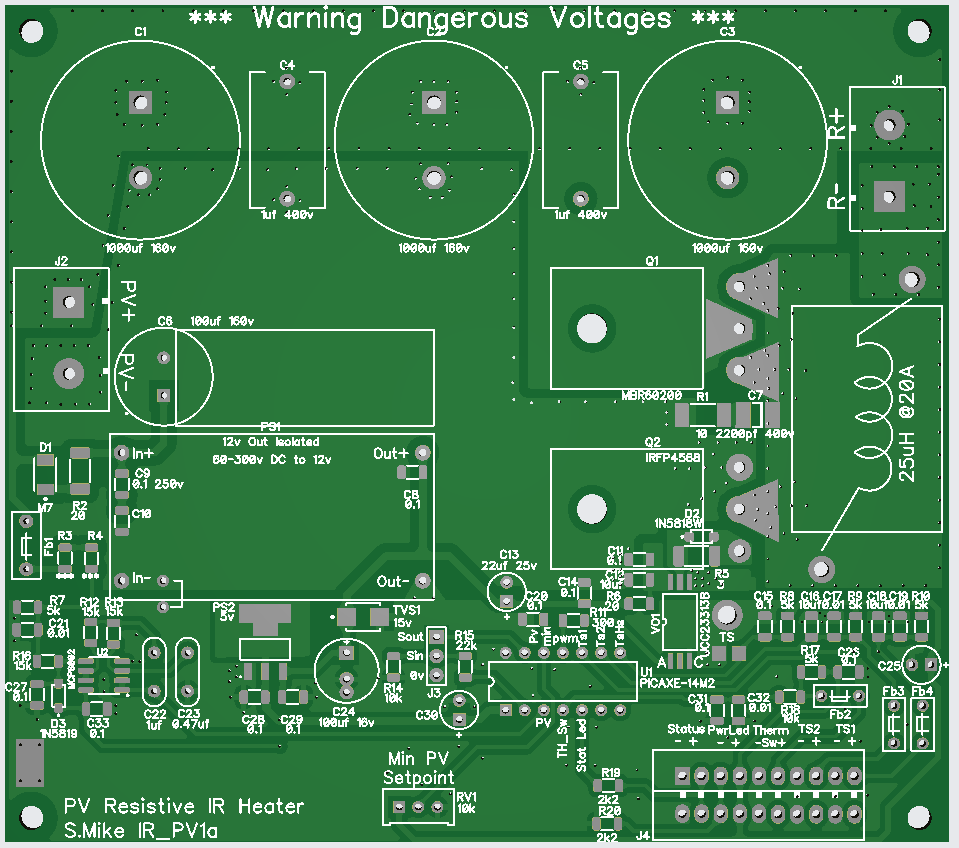
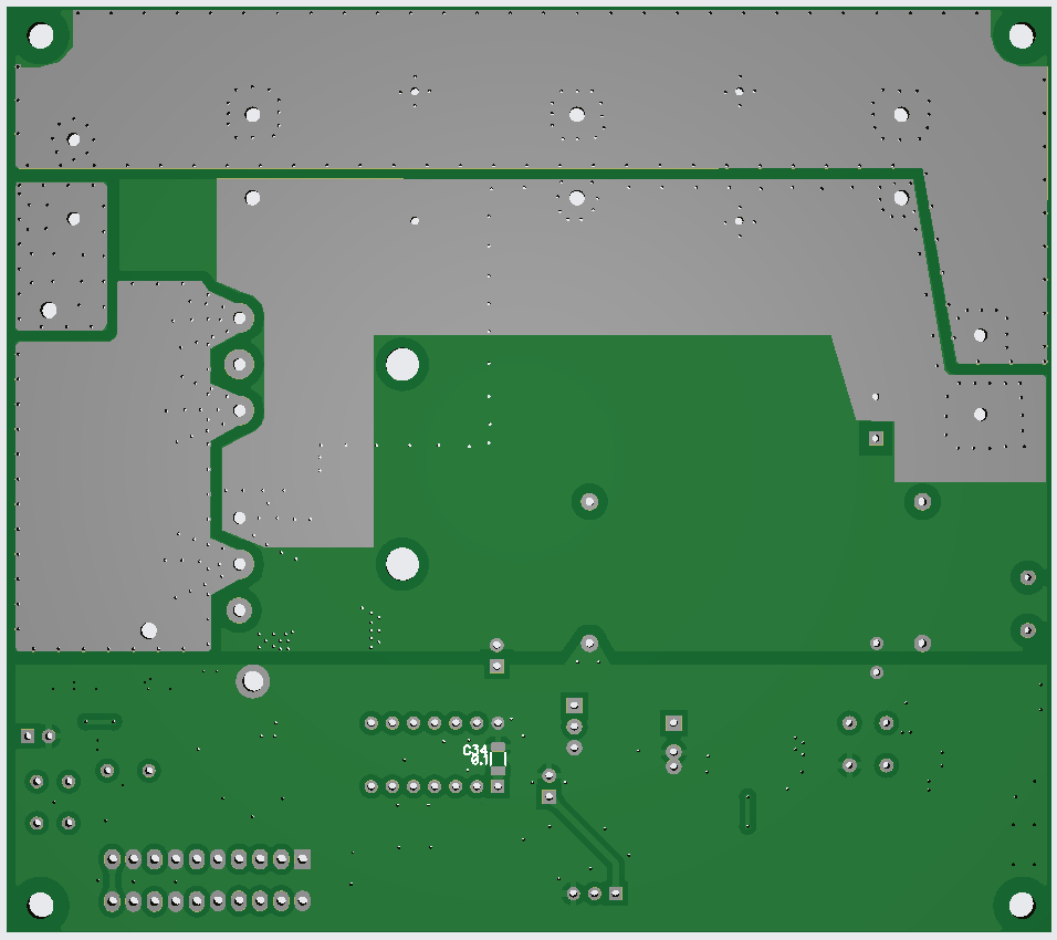
Have designed a PCB, don't have a schematic as yet but will do that before I send the gerbers off. Basically a type of upside down buck voltage reducer with no output capacitors, running PWM approx 10 khz with CPU controlled duty to keep the PV voltage near the arrays mppt value. PCB has provision for a standard wall mounted thermostat switch and a couple of NTC thermistors for sensing the heating panel(s) temperatures, mppt value is set by a 20t trim pot. Power mosfet and catch rectifier mount under the pcb.
Will draw up the schematic next..
PCB 112 x 126mm:
Cheers
Mike |
| |
Solar Mike
Guru
Joined: 08/02/2015
Location: New ZealandPosts: 1254 |
| Posted: 01:17am 31 May 2026 |
Copy link to clipboard |
Print this post |
|
Drawn up enough of the schematic to establish no errors on the pcb, haven't included the CPU in the drawing as its marked up on the pcb.
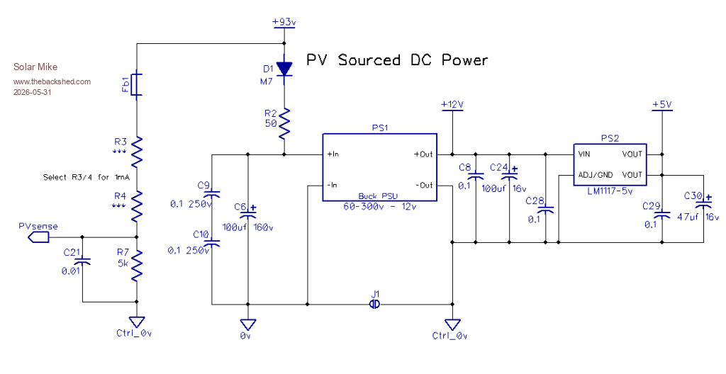
Power: All run off the PV, the PV voltage will shift dramatically, the cpu power is via a diode so will fluctuate less so.
PV voltage sensing, set up resistors for 1mA, depending on slightly higher than max unloaded PV voltage, I'm using 130v so total R of 130k.
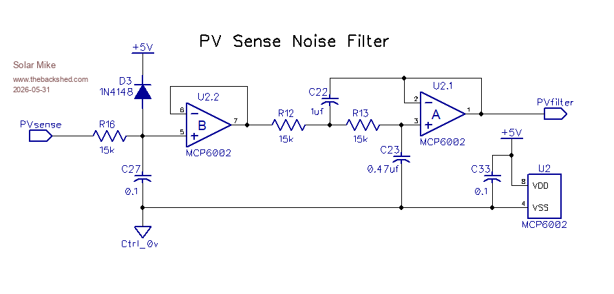
PV Sense Filter: 3 stage Low pass filter around 10hz will eliminate most RFI switching noise and allow stable mppt operation.
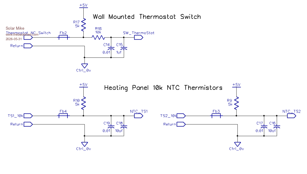
External Thermostat and heating panel NTC resistor sensing.
Probable run shielded wires or twisted pair to thermistors.
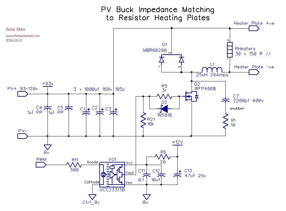
Buck power stage, using "E-Diode" mosfet driver, single 200v mosfet and dual catch diode, wind inductor on one of those MS225125-2 sendust cores, not too worried about ripple current here 25-50uH should be plenty; just want to slow down the sharp on\off transitions to more triangular waveform. Use around 10Khz PWM for lower ripple current on the 3 x 1000uf electro's rather than slow high current "bit bang" operation.
I made something similar to this a few years ago to heat a hot water element from 240 Vdc pv array, used a 555 timer and 10,000uf 400v capacitor, worked pretty well; but requiring a thermostat and thermistor heat sensing, its easier to use a $5 cpu. Will see how this performs, by the time I make up the heater panels it may be easier to gut and use a $40 reflector type dual bar heater and place all the PV panels in series for 200v.
Cheers
Mike
 |
| |
Revlac

Guru
Joined: 31/12/2016
Location: AustraliaPosts: 1307 |
| Posted: 12:06am 19 Jun 2026 |
Copy link to clipboard |
Print this post |
|
I had though that the heating lamps might be a better in some places than the resister heating plate, then I looked at the price of those food heating lamps... cost a little more than I though they should. 
Cheers Aaron
Off The Grid |
| |
Godoh
Guru
Joined: 26/09/2020
Location: AustraliaPosts: 705 |
| Posted: 02:26am 19 Jun 2026 |
Copy link to clipboard |
Print this post |
|
Hi Aaron, how about just using the infra red lamps that are used in bathroom heaters.
They are fairly cheap, and don't pull an enormous amount of power to heat the person sitting or standing under them
Pete |
| |
Solar Mike
Guru
Joined: 08/02/2015
Location: New ZealandPosts: 1254 |
| Posted: 02:31am 19 Jun 2026 |
Copy link to clipboard |
Print this post |
|
I also thought of using an IR mains power wall heater, they have a resistive element inside a long quartz glass tube + reflector; but would have to modify the resistance wire or use a higher PV voltage.
PCB's have arrived back, local sheet metal engineer is going to cut out some 2mm alloy sheet for me; plates will be 1100 x 500mm with 4 edges 50mm high folded, resistors bolt on the back under a layer of insulation, so little heat is lost upwards. Lower surface painted black etch paint, suspended from ceiling. |
| |

 Notice. New forum software under development. It's going to miss a few functions and look a bit ugly for a while, but I'm working on it full time now as the old forum was too unstable. Couple days, all good. If you notice any issues, please contact me.