Notice. New forum software under development. It's going to miss a few functions and look a bit ugly for a while, but I'm working on it full time now as the old forum was too unstable. Couple days, all good. If you notice any issues, please contact me.
rgormley Senior Member Joined: 22/02/2006 Location: AustraliaPosts: 245
Posted: 04:14am 14 Mar 2011
Copy link to clipboard
Print this post
Hi Guys,
Thinking of upping the pv panels on my system, 2035w (11 x 185w panels)
my inverter is Fronius IG 30 see specs below
it says the max pv input is 3600W and inverter has max output of 2650W
Q: i presume loses on efficiency in the inverter?
the max volatage is 500v and mpp voltage is 400
Q: the max open cct voltage is when it will blow up?
i saw today on the Fronius LCD screen max PV voltage of 284V
Q: is this the MPP voltage? ie 284 divided by 11 panels each mpp panel voltage of 25.81V
now the big question... how many more panels can i add and how? (series/parr ??)
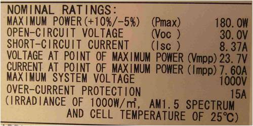
the panels i`m looking at adding are 180w (see specs below)
Q: i presume the biggest factor is the MPP voltage?
Q: or should i be worried about the MAX voltages?
going by the panels specs the mpp 23.7v (see below)
Q: 16 panels in series would be safe (16 X 23.7Volt = 379.20 mpp volts)
Q: max voltage would be max open voltage of 30v x 16panels= 480volts
hope this makes sense?
Input Characteristics of my IG 30 inverter
MPP voltage range 150 - 400 V
Max input voltage at 1000W/m�; 10�C 500 V
PV System output 2500 - 3600 Wp
Max input current 19.0 A
Output Characteristics
Nominal output 2500 W
Max power output 2650 W
Max efficiency 94.3 %
Mains voltage / frequency 230 V / 50 Hz
Distortion factor < 3.5 %
Power factor 1
Power consumption at night 0 W
General Data
Dimensions 500L x 435W x 225H mm
Weight 12 kg
Cooling Controlled forced air cooling
Ambient temperature -20�C - 50�C
Permissible humidity 0 - 95 %
Housing variations designer internal housing; optional outdoor housing
Protective Devices
DC Insulation measurement Warning at RISO < 500 k Ohm
Polarity Reverse protection Built-in
Behavior on DC overload Displacement of operating point
panels specs
KarlJ Guru Joined: 19/05/2008 Location: AustraliaPosts: 1178
Posted: 11:16am 24 Mar 2011
Copy link to clipboard
Print this post
OK limiting factor is the VOC
aim for panel voltage max VOC x 1.2 to be under the 500V
EG the panels you have with VOC of 30 V
15 would be 15 x 30 X 1.2 =540V BANG!
thus 13 would be max in a single string.
Max input current at 19A is next
theoretically it controls this itself if you run more by driving the panel voltage higher to limit input current.
your panels at 7.6A normally would run max 2 strings of 13 panels
=26 x 180W = 4680W. for realistic output multiply by 0.8
=3744W
now as your inverter is rated for max 2650 I'd be thinking there would be quite a lot of clipping at this level, ie the inverter unable to convert enough power and a significant amount being wasted.
10 x 2 on the other hand is 2880W less inverter efficiency of a few % =2700W Peak AC which is going to be running it flat out most of the time - which is great.
and min would be ~7 or 8 panels.
Make sure its in the shade with plenty of airflow and it WILL do this all day every day
If anyone makes a top notch inverter, its Fronius (they cost a bomb too).
Nice work indeed
2 strings of 7, 8, 9 would also be AOK.
Edited by KarlJ 2011-03-25Luck favours the well prepared
rgormley Senior Member Joined: 22/02/2006 Location: AustraliaPosts: 245
Posted: 11:48am 24 Mar 2011
Copy link to clipboard
Print this post
thanks Karl....
ok i actually have put them last week, 15 in series.....
the highest voltage from the panels on a nice 20 degree cloud "edge" midday effect day was 394v and the peak watts was 2792.
you say a VOC factor of 1.2 (30 * 15 * 1.2= 540v =bang!)
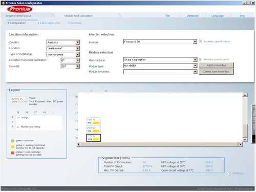
i used the fronius configuration tool imputing all the bits it wanted (including my
actual sharp models) and it came back at 15 panels. as the perfect match to the IG30
Also noted a spec sheet for the panels said the max VOC of 30.2v was at 1 degree
how much more volts do these panels make at say -5 degrees (cold Melbourne morning)
**panel temperature coefficients**
sharp panel spec sheet says -104Mv per deg based on 25deg
so is my math correct...
0 degrees would be 104Mv X 25degree =2600mv (divide by 100 to get volts) =2.6v extra volts per panel on a 0 degree morning (sun on panels)
so 30volts + 2.6volt X 15 panels=489 volts (safe for inverter)
is this correct or am i missing something....
KarlJ Guru Joined: 19/05/2008 Location: AustraliaPosts: 1178
Posted: 09:35am 27 Mar 2011
Copy link to clipboard
Print this post
Voc is normally experssed at 25degrees so if it is 30V at 1 degree then 15x30 is 450V and should be OK.
I hope all your gear is appropriately rated - normal TPS is only rated at 450V once secondary insulation is stripped back and the Aust std say it must be 1.2x higher rated. SDI (Single double insulated) cable is often used as its rating is typically 1000V.
Same for your isolator should be rated to 1.2x VOC which means std 500V isolators are not legal.
CMS has 800V breakers cheap
http://www.carbonmanagement.com.au/shop/shopdisplayproducts. asp?id=5&cat=Accessories
and if it were me -i'd do it! DC breakers have been known to fail when operated incorrectly.
As for the -5 mornings it wont matter as the it will be more like 30W/m2 vs the 1000W/m2 that the figure is derived from.
Only issue normally is shutdown on a 10 degree day during grid outage, and edge effect peak to push it up and pop.
Given their own design tool says its OK, then I guess its OK Luck favours the well prepared