
|
|
Forum Index : Microcontroller and PC projects : PicoMite and MODBUS
| Author | Message | ||||
| Volhout Guru Joined: 05/03/2018 Location: NetherlandsPosts: 5994 |
Hi All, This is by no means a complete project, it is a tool I needed for my job, and since the IT department is very restrictive on open source tools (read: cost = 0) installed on the companies computers, I hacked together a tool that uses a pico to connect to a modbus client. MODBUS TERMINAL The program uses a standard picomite (non-VGA, although it will run on a VGA) and should be controlled from a terminal program like PUTTY or TERATERM. 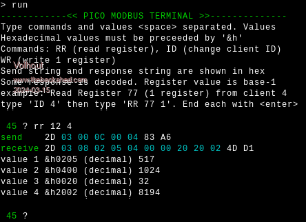 It uses ANSI colors to highlight the PDU (the payload). 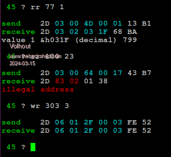 I have implemented only the commands I need for this project. That is READ HOLDING REGISTER and WRITE SINGLE REGISTER but other commands can be added when needed. The hardware interface is this (I only had a 5V RS485 interface chip, if you have a 3.3V capable chip you can ommit R2 and R3). For long cables you want to add a 100 ohm resistor (termination) between A and B. But for my bench test this is fine. 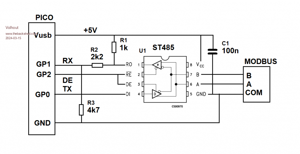 The program is attached. I originally wanted to use interrupts for the receive side, but at higher baudrates this caused too many delays (since I control the DE pin from MMBasic). It is tested up to 115200 baud (default is 19200). I hope this is to someones use.... Volhout P.S. In my version, mor commands are implemented, but these reveal customer specific information, like the way to use a password to get into factory settings. These are removed from the version below. 'experiments for modbus RTU for commincation with VFD ' version can do ' 1 correct CRC calculation for modbus ' 2 send UART and control DE ' 3 assemble correct string for read register command ' 4 receives response from holding register read, no interrupt ' 5 pullup RX -> no BREAK, write 1 reg, help text, fault explain ' 6 t.b.d. option default integer option base 1 'ansi colors bl$=chr$(27)+"[36m" wh$=chr$(27)+"[37m" gr$=chr$(27)+"[32m" rd$=chr$(27)+"[31m" 'help strings rec$=gr$+"receive "+wh$ snd$=gr$+"send "+wh$ dim er$(4) length 16 = ("illegal function","illegal address","illegal value","slave fail") 'defaults for this modbus slave const bitrate=19200 'communication speed ID=45 'default modbus id 'init system openport 'serial port helptext 'show helptext on terminal 'repeated send string (old loop) do e$="" flush_rx parse pause 50 'just some time for a message to get in if loc(1) then e$=e$+input$(loc(1),#1) 'get answer 'e$=right$(e$,len(e$)-1) 'if needed strip break character during transmit print rec$;:prtx e$ decode e$ loop sub decode a$ local value,numbyte,i select case asc(mid$(a$,2,1)) case 03 'read numbyte=asc(mid$(a$,3,1)) for i=4 to 2+numbyte step 2 value=256*ASC(mid$(a$,i,1))+ASC(mid$(a$,i+1,1)) print "value";(i-2)/2;" &h";right$("000"+hex$(value),4);" (decimal)";value next case >127 'error print rd$;er$(asc(mid$(a$,3,1)));wh$ end select end sub 'this is the command loop, parsing text entered sub parse print : print gr$;ID;wh$;" "; : input txt$ : txt$=UCASE$(txt$) if left$(txt$,2)="ID" then ID=val(mid$(txt$,4)) 'robust if left$(txt$,2)="RR" then modsend mk_rd$(txt$) : print snd$;:prtx tx$ if left$(txt$,2)="WR" then modsend mk_wr$(txt$) : print snd$;:prtx tx$ end sub 'compiles the string for reading 16 bit holding register function mk_rd$(a$) local posi=4:hlp$=right$(a$,len(a$)-3) 'strip the function code 'register number and registeer range are 2 byte MSB first mk_rd$=chr$(ID)+chr$(3) 'ID + the modbus read register function 3 'get register number, and strip from string reg=val(hlp$):posi=instr(hlp$," "):if posi>1 then hlp$=right$(hlp$,len(hlp$)-posi) 'reg = reg - 1 'register start at 1 .... not used in documentation copeland mk_rd$=mk_rd$+chr$(reg\256)+chr$(reg and 255) 'get number of register to read num=val(hlp$) mk_rd$=mk_rd$+chr$(num\256)+chr$(num and 255) end function 'compiles the string for writing a single 16 bit register function mk_wr$(a$) local posi=4:hlp$=right$(a$,len(a$)-3) 'strip the function code 'register number and registeer range are 2 byte MSB first mk_wr$=chr$(ID)+chr$(6) 'ID + the modbus rwrite register function 6 'get register number, and strip from string reg=val(hlp$):posi=instr(hlp$," "):if posi>1 then hlp$=right$(hlp$,len(hlp$)-posi) 'reg = reg - 1 'register start at 1 .... not used in documentation copeland mk_wr$=mk_wr$+chr$(reg\256)+chr$(reg and 255) 'get the value to write to the register num=val(hlp$) mk_wr$=mk_wr$+chr$(num\256)+chr$(num and 255) end function 'prints the string send from UART in readable form on console sub prtx a$ local i for i=1 to len(a$) if i=2 then print choice(asc(mid$(a$,i,1))>127,rd$,bl$); if i=len(a$)-1 then print choice(check(a$),wh$,rd$); print right$("0"+hex$(asc(mid$(a$,i,1))),2);" "; next print wh$ end sub 'sends ID+PDU in string a$, adds CRC16 sub modsend a$ local m$=a$ 'calculate string crc and append crc to string crc_val=math(crc16 m$,len(m$),&h8005,&hffff,0,1 ,1) crcl=crc_val and 255:m$=m$+chr$(crcl) crch=crc_val \ 256:m$=m$+chr$(crch) 'calculate DE time ms_char!=11*1000/bitrate '1 char = 11 bits (start+8+parity+stop) ms_mess!=len(m$)*ms_char! 'message total time 'send it through the UART with controlled DE pin pin(gp2)=1 'DE high print #1,m$; pause ms_mess! pin(gp2)=0 'DE low tx$=m$ 'global string, just for debugging end sub 'opens the UART port for communication and the direction cotrol DE sub openport 'open COM1 port with modbus defaults 19200/8bit/even parity/1 stop setpin gp1, gp0, COM1 'rx,tx,port setpin gp2,dout : pin(gp2)=0 'DE pin is GP2 'open "COM1:"+str$(bitrate)+",256,have_data,EVEN" as #1 'interrupt driven open "COM1:"+str$(bitrate)+",EVEN" as #1 end sub 'checks if e received strin has matchin CRC in it function check(a$) local pd$,cr$ local crc_pd,crc_mes check=0 if len(a$)>3 then 'separate ID/PDU from message pd$=left$(a$,len(a$)-2) crc_pd=math(crc16 pd$,len(pd$),&h8005,&hffff,0,1 ,1) 'separate CRC from message cr$=right$(a$,2) crc_mes=256*asc(right$(cr$,1))+asc(left$(cr$,1)) 'compare CRC's -> when equal, message is okay. if crc_mes=crc_pd then check=1 end if end function 'flush the USRT rx buffer sub flush_rx local dum$ 'print loc(1) if loc(1) then dum$=input$(loc(1),#1) end sub sub helptext print gr$+"------------<< PICO MODBUS TERMINAL >>--------------" print "Type commands and values <space> separated. Values " print "Hexadecimal values must be preceeded by '&h'" print "Commands: RR (read register), ID (change client ID) " print "WR (write 1 register) print "Send string and response string are shown in hex" print "Some response is decoded. Register value is base-1" print "example: Read Register 77 (1 register) from client 4" print "type 'ID 4' then type 'RR 77 1'. End each with <enter>" end sub Edited 2024-03-15 22:45 by Volhout PicomiteVGA PETSCII ROBOTS |
||||
| Ossi Newbie Joined: 22/06/2023 Location: GermanyPosts: 6 |
Hi Volhout, This is great work. I had already tried to read the data from my solar inverter to control my loads in the house. My automation runs on atmega32 and is written in assembler, so I had problems with the CRC calculation. So far I only listen the traffic between the inverter and the power meter to get a few values. Reading many more values in the future with a PicoW directly from the inverter is a cheap and elegant solution. Thanks for the publication. Ossi |
||||
| Volhout Guru Joined: 05/03/2018 Location: NetherlandsPosts: 5994 |
Dear Ossi, I am glad it works for you. Volhout PicomiteVGA PETSCII ROBOTS |
||||
| Volhout Guru Joined: 05/03/2018 Location: NetherlandsPosts: 5994 |
This is an updated version of the MODBUS RTU terminal. - When PicoMiteVGA then the VGA screen is used as terminal - When PicoMite then Teraterm/Putty is treated as the terminal - Implemented write to multiple registers (WM) and write of a string to a single register (WS). This is the code. 'experiments for modbus RTU for commincation with VFD ' version can do ' 1 correct CRC calculation for modbus ' 2 send UART and control DE ' 3 assemble correct string for read register command ' 4 receives response from holding register read, no interrupt ' 5 pullup RX -> no BREAK, write 1 reg, help text, fault explain ' 6 write multiple ' 7 write string according Customer procedure (modbus ??) werkt ' WS reg DIT_IS_DE_TEXT format. ' 8 VGA color option default integer option base 1 'check if main output is VGA screen or console vga=(mm.device$="PicoMiteVGA") 'ansi colors bl$=chr$(27)+"[36m" wh$=chr$(27)+"[37m" gr$=chr$(27)+"[32m" rd$=chr$(27)+"[31m" 'help strings rec$="receive " snd$="send " dim er$(4) length 16 = ("illegal function","illegal address","illegal value","slave fail") 'defaults for customer VFD const bitrate=19200 'communication speed ID=45 'default modbus id 'init system openport 'serial port cls helptext 'show helptext on terminal 'repeated send string (old loop) do e$="" flush_rx parse pause 50 'just some time for a message to get in if loc(1) then e$=e$+input$(loc(1),#1) 'get answer 'e$=right$(e$,len(e$)-1) 'if needed strip break character during transmit if vga then color rgb(green):print rec$;:color rgb(white) else print gr$;rec$;wh$; end if prtx e$ decode e$ loop sub decode a$ local value,numbyte,i select case asc(mid$(a$,2,1)) case 03 'read numbyte=asc(mid$(a$,3,1)) for i=4 to 2+numbyte step 2 value=256*ASC(mid$(a$,i,1))+ASC(mid$(a$,i+1,1)) print " reg";reg-1+(i-2)/2;" = &h";right$("000"+hex$(value),4);" (decimal)";value next case >127 'error if vga then color rgb(red):print er$(asc(mid$(a$,3,1))):color rgb(white) else print rd$;er$(asc(mid$(a$,3,1)));wh$ end if end select end sub 'this is the command loop, parsing text entered sub parse if vga then color rgb(green):print ID;" ";:color rgb(white) else print gr$;ID;" ";wh$; end if input txt$ : txt$=UCASE$(txt$) select case left$(txt$,2) case "RR" modsend mk_rd$(txt$) case "WR" modsend mk_wr$(txt$) case "WM" modsend mk_wm$(txt$) case "WS" modsend mk_ws$(txt$) end select if left$(txt$,2)="ID" then ID=val(mid$(txt$,4)) else if vga then color rgb(green):print snd$;:color rgb(white) else print gr$;snd$;wh$ end if prtx tx$ end if end sub 'compiles the string for reading 16 bit holding register function mk_rd$(a$) local posi=4:hlp$=right$(a$,len(a$)-3) 'strip the function code 'register number and registeer range are 2 byte MSB first mk_rd$=chr$(ID)+chr$(3) 'ID + the modbus read register function 3 'get register number, and strip from string reg=val(hlp$):posi=instr(hlp$," "):if posi>1 then hlp$=right$(hlp$,len(hlp$)-posi) 'reg = reg - 1 'register start at 1 .... not used in documentation mk_rd$=mk_rd$+chr$(reg\256)+chr$(reg and 255) 'get number of register to read num=val(hlp$) mk_rd$=mk_rd$+chr$(num\256)+chr$(num and 255) end function 'compiles the string for writing a single 16 bit register function mk_wr$(a$) local posi=4:hlp$=right$(a$,len(a$)-3) 'strip the function code 'register number and registeer range are 2 byte MSB first mk_wr$=chr$(ID)+chr$(6) 'ID + the modbus write register function 6 'get register number, and strip from string reg=val(hlp$):posi=instr(hlp$," "):if posi>1 then hlp$=right$(hlp$,len(hlp$)-posi) 'reg = reg - 1 'register start at 1 .... not used in documentation mk_wr$=mk_wr$+chr$(reg\256)+chr$(reg and 255) 'get the value to write to the register num=val(hlp$) mk_wr$=mk_wr$+chr$(num\256)+chr$(num and 255) end function 'compiles the string for writing multiple 16 bit registers function mk_wm$(a$) local posi=4:hlp$=right$(a$,len(a$)-3) 'strip the function code 'register number and registeer range are 2 byte MSB first mk_wm$=chr$(ID)+chr$(16) 'ID + the modbus rwrite register function 6 'get register number, and strip from string reg=val(hlp$):posi=instr(hlp$," "):if posi>1 then hlp$=right$(hlp$,len(hlp$)-posi) 'reg = reg - 1 'register start at 1 .... not used in documentation mk_wm$=mk_wm$+chr$(reg\256)+chr$(reg and 255) 'get register count, and strip from string num=val(hlp$):posi=instr(hlp$," "):if posi>1 then hlp$=right$(hlp$,len(hlp$)-posi) mk_wm$=mk_wm$+chr$(num\256)+chr$(num and 255)+chr$(num*2 and 255) 'values(16b)+bytes 'num is number of 16 bit values to follow for i=1 to num 'get the value to write to the register dat=val(hlp$):posi=instr(hlp$," "):if posi>1 then hlp$=right$(hlp$,len(hlp$)-posi) mk_wm$=mk_wm$+chr$(dat\256)+chr$(dat and 255) next end function 'compiles the string for writing text in one registers function mk_ws$(a$) local posi=4:hlp$=right$(a$,len(a$)-3) 'strip the function code 'register number and registeer range are 2 byte MSB first mk_ws$=chr$(ID)+chr$(06) 'ID + the modbus write single register function 6 'get register number, and strip from string reg=val(hlp$):posi=instr(hlp$," "):if posi>1 then hlp$=right$(hlp$,len(hlp$)-posi) 'reg = reg - 1 'register start at 1 .... not used in documentation mk_ws$=mk_ws$+chr$(reg\256)+chr$(reg and 255) 'rest of the command string is text, append it 'I am not sure this is MODBUS compliant, but customer uses it this way mk_ws$=mk_ws$+hlp$ end function 'prints the string send from UART in readable form on console sub prtx a$ local i for i=1 to len(a$) if i=2 then if vga then color choice(asc(mid$(a$,i,1))>127,rgb(red),rgb(cyan)) else print choice(asc(mid$(a$,i,1))>127,rd$,bl$); end if end if if i=len(a$)-1 then if vga then color choice(check(a$),rgb(white),rgb(red)) else print choice(check(a$),wh$,rd$); end if end if print right$("0"+hex$(asc(mid$(a$,i,1))),2);" "; next if vga then print :color rgb(white) else print wh$ end if end sub 'sends ID+PDU in string a$, adds CRC16 sub modsend a$ local m$=a$ 'calculate string crc and append crc to string crc_val=math(crc16 m$,len(m$),&h8005,&hffff,0,1 ,1) crcl=crc_val and 255:m$=m$+chr$(crcl) crch=crc_val \ 256:m$=m$+chr$(crch) 'calculate DE time ms_char!=11*1000/bitrate '1 char = 11 bits (start+8+parity+stop) ms_mess!=len(m$)*ms_char! 'message total time 'print ms_mess! 'debug 'send it through the UART with controlled DE pin pin(gp2)=1 'DE high print #1,m$; pause ms_mess! pin(gp2)=0 'DE low tx$=m$ 'global string, just for debugging end sub 'opens the UART port for communication and the direction cotrol DE sub openport 'open COM1 port with modbus defaults 19200/8bit/even parity/1 stop setpin gp1, gp0, COM1 'rx,tx,port setpin gp2,dout : pin(gp2)=0 'DE pin is GP2 open "COM1:"+str$(bitrate)+",EVEN" as #1 end sub 'checks if e received strin has matchin CRC in it function check(a$) local pd$,cr$ local crc_pd,crc_mes check=0 if len(a$)>3 then 'separate ID/PDU from message pd$=left$(a$,len(a$)-2) crc_pd=math(crc16 pd$,len(pd$),&h8005,&hffff,0,1 ,1) 'separate CRC from message cr$=right$(a$,2) crc_mes=256*asc(right$(cr$,1))+asc(left$(cr$,1)) 'compare CRC's -> when equal, message is okay. if crc_mes=crc_pd then check=1 end if end function 'flush the USRT rx buffer sub flush_rx local dum$ 'print loc(1) if loc(1) then dum$=input$(loc(1),#1) end sub sub helptext if vga then color rgb(green) else print gr$; Print "-----------<< PICO MODBUS RTU TERMINAL >>-------------" if vga then color rgb(white) else print wh$; Print "Type commands and values <space> separated values." Print "Hexadecimal values must preceeded '&h'. Commands :" Print "ID (change client ID) = ID xx " Print "RR (read registers) = RR reg num" Print "WR (write 1 register) = WR reg val" Print "WM (write multi registers)= WM reg num val1 val2 .." Print "WS (write text string) = WS reg TEXT_STRING" Print "Send string and response string are shown in hex" Print "Some response is decoded. Register value is base-1" Print "example: Read Register 77 (1 register) from client 4" Print "type 'ID 4' then type 'RR 77 1'. End each with <enter>" end sub PicomiteVGA PETSCII ROBOTS |
||||
| Volhout Guru Joined: 05/03/2018 Location: NetherlandsPosts: 5994 |
New release with minor changes. Up to now I used a PicoMiteVGA for the job. For field work, I created a adaptor cable for the laptop, using a RP2040-ZERO and a RS485 interface chip. Use TeraTerm or Putty, since these support the ANSI colors in the terminal window. The WS2812 LED on the zero shows status GREEN = OK CYAN = waiting for answer (no response) RED = MODBUS failure Code: modbus12.zip Photo of actual interface before sleeving:  Volhout Edited 2024-07-03 19:39 by Volhout PicomiteVGA PETSCII ROBOTS |
||||
| Mixtel90 Guru Joined: 05/10/2019 Location: United KingdomPosts: 8965 |
That's very neat. :) Mick Zilog Inside! nascom.info for Nascom & Gemini Preliminary MMBasic docs & my PCB designs |
||||
| Volhout Guru Joined: 05/03/2018 Location: NetherlandsPosts: 5994 |
Mick, others, Implemented timeout and retries. Normally these would not be needed for manual interaction, but I needed it for some of the recent clients. Defines of timeout and retries are in the MMBasic program. Modify at will. 'modbus defines looptime=50 'ms timeout=1000 'ms loops=timeout/looptime 'number of loops in 1000ms retries=5 'number of retries modbus13.zip Volhout Edited 2024-07-03 20:52 by Volhout PicomiteVGA PETSCII ROBOTS |
||||
| Volhout Guru Joined: 05/03/2018 Location: NetherlandsPosts: 5994 |
All, Is there anyone with experience with MODBUS in the field ? I am running into a problem that I would like to reflect on you. A MODBUS RTU system consists of a master and several slaves (Mutli-master is also possible, but that is not important here) connected to a RS485 bus. The protocol is a question/amswer protocol. The master asks, the slave responds. 1/ In case you have a slave that has a holding register, you can write a 16 bit value to the slave. The slave responds by echoing the same message back to the master. The master sees this as a confirmation of a succesfull write. 2/ In case the slave is turned off, the master get's no response. And the master re-sends the same command (hoping this time there is a response). If I monitor the bus (bus spy) the messages over this bus are identical. I cannot see any difference between a good working slave, or a slave that is switched off. Unless I have access to the master. Is there anyone with experience, that can tell me how to go forward ? Volhout Edited 2025-03-19 23:50 by Volhout PicomiteVGA PETSCII ROBOTS |
||||
| lizby Guru Joined: 17/05/2016 Location: United StatesPosts: 3816 |
Hmmm. I'm not sure I have experience with MODBUS which is relevant to your question, but I'm using Annex RDS on an ESP32-C3SuperMini with an RS485 MODBUS RTU module to talk to a PZEM-017 DC Current Monitor. Link here to what I have done, but all the magic is concealed within the Annex firmware. From the point of view of my Annex Basic code, it's a call and response methodology. ~ Edited 2025-03-20 01:53 by lizby PicoMite, Armmite F4, SensorKits, MMBasic Hardware, Games, etc. on FOTS |
||||
| RetroRamJet Newbie Joined: 21/05/2024 Location: United StatesPosts: 1 |
I have seen Modbus Masters programmed to provide a 1-bit heartbeat dither to monitor slave activity. So you have to dedicate a single bit, say LSB, as the heartbeat. For a Holding register value that is used to indicate an analog value such as VFD speed command, the scaling is arranged such that the LSB dither is an insignificant change. The Master sends a holding register command with the LSB set. If there is no response the Master resends with the LSB cleared. A bus spy will either see a repeat dither bit value (Slave up and responding), or an alternating LSB in the message indicating a non-responding slave. Not really a standard Modbus behavior, but if you have full control of the Master programming then it should be able to work. Another common trick is for the slave to provide an incrementing value on each Master request of a particular holding register. The bus spy server can monitor this and throw an alarm if the value stops incrementing. Loss of Modbus comms has always been problematic - what do you do when it is detected; freeze values and throw an alarm, or dump the process? |
||||
| Marcel27 Senior Member Joined: 13/08/2024 Location: NetherlandsPosts: 104 |
Great work Volhout,  In the past I made a modbus library for the Alpha Five database software. It collected data from a PLC (Koyo D0-06DR) I used to control my home floor heating with 7 valves. That was years ago... I'm glad I forgot everything. However it was nice working at it  . The PLC got damaged from a lightning strike 2 houses away in 2015. Since then everything has been running in the old way again with 1 valve. . The PLC got damaged from a lightning strike 2 houses away in 2015. Since then everything has been running in the old way again with 1 valve.Marel27 |
||||
| Volhout Guru Joined: 05/03/2018 Location: NetherlandsPosts: 5994 |
Hi Marcel, That has been my motto for decades. "The simpler, the better". Last autum I had a colleague telling me he has spend many evenings in updating his home automation system to the latest firmware, and finally everything worked again. He did really have couplings between everything (except the fridge). Heating\cooling, lighting, alarm system, ventilation, solar, blinds. An exceptional system, and complex with purchased systems coupled to homebrew systems. Really impressive (I think the Dutch "huis van de toekomst" would have looked pale next to this). (english = "house of the future", a building from 1989 that demo's what automation can be done in a house, it had solar heating, voice control for everything). I asked him a simple question: "when you are on business trip, and the system stops working on a cold day, can your wife restart it ? Or is she forced to move into a hotel until you return ?" Uh...uh... Volhout P.S. I found a solution. When the master repeats after a timeout, the time for the slave to respons has passed. So based on timestamp in the modbus spy, you can decide wether it is a master repeat, or a slave reply. To find the timout value, you have to switch off one slave for a few seconds. Then turn it on again. . Edited 2025-03-20 17:51 by Volhout PicomiteVGA PETSCII ROBOTS |
||||
| lizby Guru Joined: 17/05/2016 Location: United StatesPosts: 3816 |
This is a really big issue. There is no way my wife will do the kind of fiddling that I do. So the fallback is that everything can work as it originally did--all of the other stuff is supplemental. It is a profound technological achievement that electricity in the home "just works" (until it doesn't), and that heating and cooling can be had by just pressing a few buttons on a thermostat. Congratulations on finding a solution to your problem. PicoMite, Armmite F4, SensorKits, MMBasic Hardware, Games, etc. on FOTS |
||||
| PhenixRising Guru Joined: 07/11/2023 Location: United KingdomPosts: 2005 |
BINGO! This also (sort of) applies to process equipment and I have yet to find an example (other than my own) where this has been considered. One small example; a proximity sensor fails and so the machine is dead because there is never a spare sensor. Let's say that the actuator is a clamping device and open/close takes ~1s. I provide a parameter setting to substitute a time-delay for the sensor....to keep production rolling until they procure a replacement. If I have a problem with a CNC axis, I can have it ignored because a machine can still be useful without it.  |
||||
| Volhout Guru Joined: 05/03/2018 Location: NetherlandsPosts: 5994 |
SNOOPY Snoopy is a modbus spy. You connect it as a device to an existing MODBUS RTU system, and it lists all traffic on that bus. It is not sophisticated, but just does (only) that. Snoopy runs on a picomite. Connect a 485 driver chip (i.e. MAX485) to COM1 of the pico (GP0/GP1) and connect RE and DE pins to GP2. Same as shown in the first post. 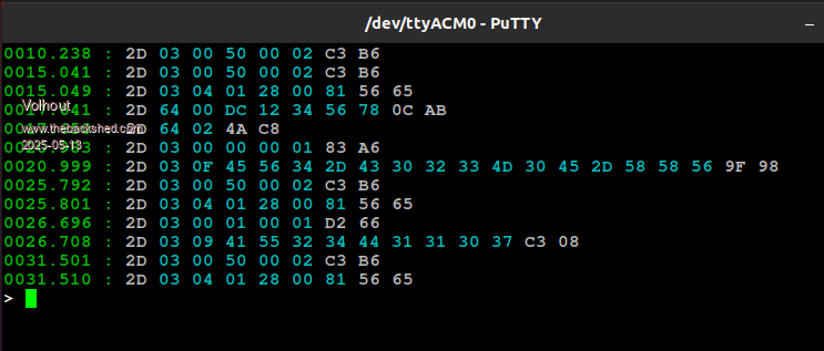 The code is simple. 'modbus spy for Pico Zero 'version control 'v01 serial snoop works, ws2812 indicates errors 'v02 added timestamping 'v03e preparations for decoding option default integer 'ansi colors bl$=Chr$(27)+"[36m" wh$=Chr$(27)+"[37m" gr$=Chr$(27)+"[32m" rd$=Chr$(27)+"[31m" 'ws2812 colors cya%=&h2030 pur%=&h300030 grn%=&h4000 red%=&h400000 'defaults for Copeland VFD's Const bitrate=19200 'communication speed ID=45 'default modbus id 'init system for ZERO using gp0/gp1/gp2 'open COM1 port with modbus defaults 19200/8bit/even parity/1 stop setpin gp1, gp0, COM1 'rx,tx,port setpin gp2,dout : pin(gp2)=0 'DE pin is GP2 Open "COM1:"+Str$(bitrate)+",EVEN" As #1 device ws2812 o,gp16,1,pur% 'gp16 is connected to the RGB color LED dim oe$ = "" , e$ = "" timout!= 2 * 11 * 1000 / bitrate 'message end = 2 characters, 11 bits each, in ms timer=0 'snoop bus do timestamp!=timout!+timer do if loc(1) then e$=e$+Input$(Loc(1),#1): timestamp!=timout!+timer loop until timer>timestamp! 'end of message when no new character for 22 bittime if len(e$)>0 then prtx e$ : oe$ = e$ : e$ = "" loop 'prints the string from UART in readable form on console Sub prtx a$ Local i print gr$;str$(timer/1000,4,3,"0");" : ";wh$; For i=1 To Len(a$) If i=2 Then Print choice(Asc(Mid$(a$,i,1))>127,rd$,bl$); If i=Len(a$)-1 Then Print choice(check(a$),wh$,rd$); Print Right$("0"+Hex$(Asc(Mid$(a$,i,1))),2);" "; Next 'try to analyze source of message 'Print space$(60-3*len(e$));bl$; 'print "h"; print wh$ End Sub 'checks if e received string has matching CRC in it Function check(a$) Local pd$,cr$ Local crc_pd,crc_mes If Len(a$)>3 Then 'separate ID/PDU from message pd$=Left$(a$,Len(a$)-2) crc_pd=math(crc16 pd$,Len(pd$),&h8005,&hffff,0,1 ,1) 'separate CRC from message cr$=Right$(a$,2) crc_mes=256*Asc(Right$(cr$,1))+Asc(Left$(cr$,1)) 'compare CRC's -> when equal, message is okay. If crc_mes=crc_pd Then check=1 : device ws2812 o,gp16,1,grn% else check=0 : device ws2812 o,gp16,1,red% end if else device ws2812 o,gp16,1,pur% End If End Function I used a RP2040 ZERO that has an on_board WS2812. It changes color with the messages on the bus. CRC fails are indicated. If you have a genuine pico, comment out the WS2812 lines. The console messages show errors in the communication in red color. Traffic analysis is not implemented (yet). Volhout Edited 2025-05-13 16:34 by Volhout PicomiteVGA PETSCII ROBOTS |
||||
| The Back Shed's forum code is written, and hosted, in Australia. | © JAQ Software 2026 |
