
|
|
Forum Index : Microcontroller and PC projects : CPUSPEED vs mA - tinkering
| Author | Message | ||||
| PhenixRising Guru Joined: 07/11/2023 Location: United KingdomPosts: 2005 |
There is also the issue of temp-rise when sinking/sourcing, right? I plan to keep this as low as possible. |
||||
| Mixtel90 Guru Joined: 05/10/2019 Location: United KingdomPosts: 8965 |
There will always be some temperature rise in GPIO because there is always some voltage drop across the mosfet. At low current it will be very little. Don't leave spare GPIO set to output as that will give some current loss through leakage. DIN with weak pullup is probably the best way as it suits both the RP2040 and the RP2350. Mick Zilog Inside! nascom.info for Nascom & Gemini Preliminary MMBasic docs & my PCB designs |
||||
| Nimue Guru Joined: 06/08/2020 Location: United KingdomPosts: 427 |
All What I love about this forum and the whole community here is how simple posts can blowup into a wider discussion over things whilst linked to the original post, exceed the question and I learn something. Enough of the love in. Off to buy some dry ice ;-) Entropy is not what it used to be |
||||
| PhenixRising Guru Joined: 07/11/2023 Location: United KingdomPosts: 2005 |
Best community ever and I will never complain about drifting off topic because time and again, I have learned something. I just wish we all lived in the same village so that we could get together over a pint  |
||||
| circuit Guru Joined: 10/01/2016 Location: United KingdomPosts: 307 |
If you are looking for really low power operation in the MMBasic series, look at the Armmite L4. The manual charts its operation at 80MHz as drawing 12.7mA ranging down to 0.8mA at 2MHz with CPU sleep at 3uA. It is a neat little chip and very useful for low power operation. The manual is here: Armmite L4 User Manual One version of the firmware is here; Armmite L4 firmware thread This may not be the latest firmware version; I cannot see the version listing. As far as I know the last version that Peter produced was MMBasic Ver 5.05.09. ...and the chip is available here; Available at RS |
||||
| Volhout Guru Joined: 05/03/2018 Location: NetherlandsPosts: 5994 |
Hi Nimue, As promised, here is a simple circuit, with components that you may have in your box with old junk, that can be used in conjunction with a PicoMite, to switch it ON with a button, where the Pico can turn itself off after the task is completed. The circuit draws 0.4mA when off (*) with these junk box parts. It is powered from a single LIPO cell (4.2V). 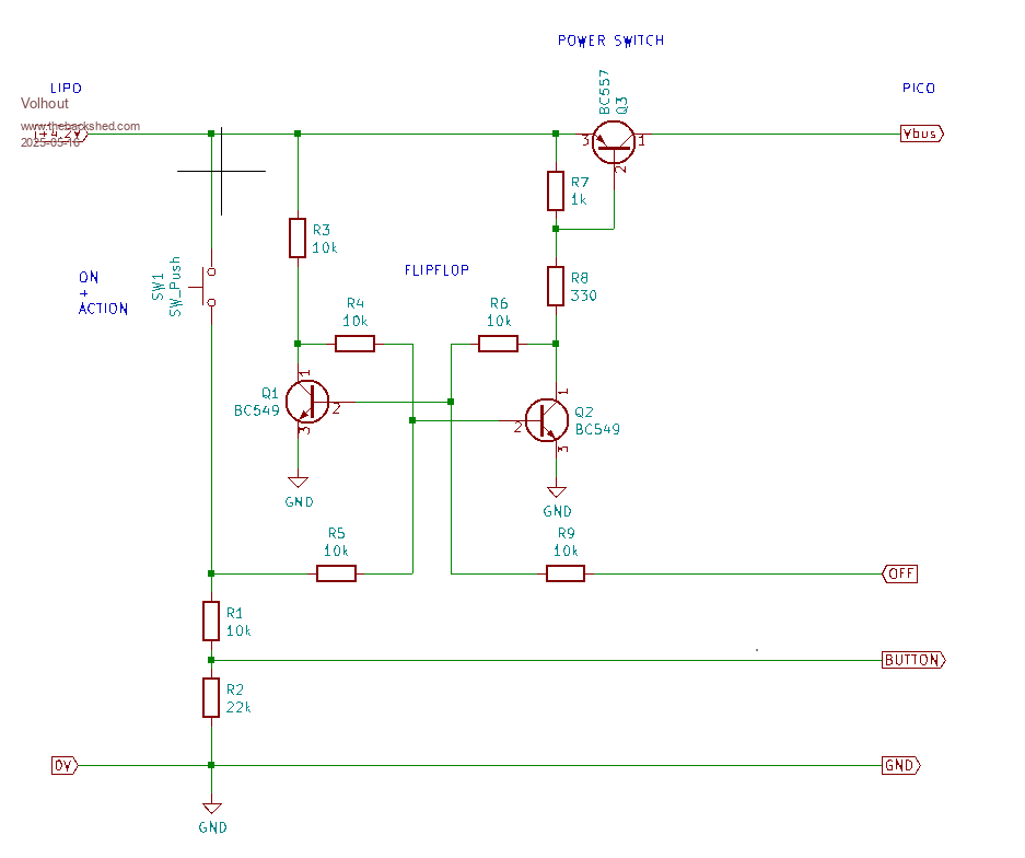 This is the demo program. It turns the pico off after 10 seconds. During operation you can use the button (multi function button) to activate functions in the program. 'ON/OFF demo 'gp6=OFF (active high) 'gp7=BUTTON (active high) 'gp0=LED acknowledge button press setpin gp0,dout : pin(gp0)=0 setpin gp6,dout : pin(gp6)=0 setpin gp7,din 'timeout timeout=10000 'ms 'this loop detects button presses until timeout timer=0 butn=1 do if butn=pin(gp7) then print choice(butn,"button pressed","button released") pin(gp0)=butn butn=1-butn 'invert pause 10 end if loop until timer>timeout 'switch off pin(gp6)=1 do : loop end This is what I had in my junk box. The circuit also works fine with 4 NiMH cells (4.8..5.2V). Just make sure you do not exceed the 5.5V max for the pico. When using a RP2350 (GPIO bug in that chip) change R1 to 4.7k and R2 to 10k. One of the disadvantages of the pico is that it takes around 2 seconds to boot. That is why I added a LED in my test circuit, connected to Vbus (not shown above). So you have confirmation that you actually pressed the button. Above program is auto started (OPTION AUTORUN ON). Volhout (*) You can replace the flipflop with 2 gates from a 74HC02 (NOR) and the BC557 with a small logic level P-FET, and then the circuit draws only few uA. But I could not find the 74HC02 in my junk box. Hence this circuit. Edited 2025-05-16 04:58 by Volhout PicomiteVGA PETSCII ROBOTS |
||||
| Volhout Guru Joined: 05/03/2018 Location: NetherlandsPosts: 5994 |
This is the low power version. Tested. 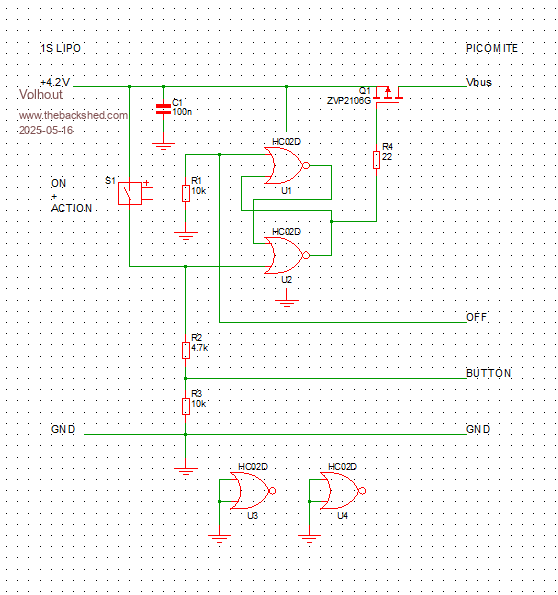 OFF is a pico output BUTTON is a pico input (only if you want to use the button in your program, in example to switch off...) Above program works identical with this hardware. Below, a picture of the circuit breadboarded (in the red circle).  Volhout PicomiteVGA PETSCII ROBOTS |
||||
| CaptainBoing Guru Joined: 07/09/2016 Location: United KingdomPosts: 2171 |
same functionality(ish?). This is the circuit I use all the time for my High Side Switch - works lovely. Currrently two of these (some parts substituted) in my data collector for sensor board and radio board to minimize battery use. https://fruitoftheshed.com/wiki/doku.php?id=circuit_ideas:soft_power_on_off The circuit as shown was originally on my Tacho - battery operated - so it turned on with a button and would turn itself off after a period of inactivity. Worked very well. The debug jumper is completely optional in the finished item but will save you ripping your hair out after 10 minutes of confusing testing just to find the thing has switched itself off and you didn't notice  @WhiteWizzard recently had a canter with HSS and found a nice little FET IRLML6401 which I have tested and adopted for my low power requirements. Edited 2025-05-16 20:01 by CaptainBoing |
||||
| Nimue Guru Joined: 06/08/2020 Location: United KingdomPosts: 427 |
Perfect - I'll give this a go with a push switch to start the process and have the Pico signal it wants to be "off" after a couple of hours. Cheers Entropy is not what it used to be |
||||
| Volhout Guru Joined: 05/03/2018 Location: NetherlandsPosts: 5994 |
I added the flipflop to avoid holding the power ON button for several seconds. Your circuit will work fine with an MX170 that starts fast. Also the flipflop will guarantee that the pico (MCU) can not restart unintended, causing endless loops, ending in an empty battery. If you would go surface mount, the circuit can get really small when using a 74LVC2G02 (2 NOR gates) and a SOT23 FET. Volhout Edited 2025-05-16 22:49 by Volhout PicomiteVGA PETSCII ROBOTS |
||||
| phil99 Guru Joined: 11/02/2018 Location: AustraliaPosts: 3323 |
CaptainBoing's circuit can latch the output on without a flipflop. Just replace Q2 with a MOSFET, decrease R2 to 1kΩ and increase C1 to 1 to 10µF. Momentarily pressing the button charges C1 holding Q1 on until the charge leaks away. If necessary you can speed that up with a bleed resistor as it could be several minutes. |
||||
| CaptainBoing Guru Joined: 07/09/2016 Location: United KingdomPosts: 2171 |
yes of course - anything that takes a while to boot will benefit from the flip-flop. In reality, even the '170-based micromites take a second or two to power-up, especially if you have LCD panels etc. configured; they aren't as "instant" as a pure (i.e. hand carved assembler) solution... There are structures and stuff that MMBasic has to substantiate before your prog gets the road. My tacho was the first to highlight this for me; push-button to start could easily be missed even if you weren't particularly quick, hence the "hold 'til the screen flashes green" instruction which was only a second or so, but... As for these litle 1G and 2G devices - I agree. So often you just need a gate or two and it's grinds my miser nerve to "waste" the spares just chained to the floor for their lives. I recently needed just two schmitt inverters - 74LVC2G14 to the rescue - tiny little 6 pin SOT and so cheap!  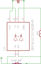 Edited 2025-05-16 23:48 by CaptainBoing |
||||
| The Back Shed's forum code is written, and hosted, in Australia. | © JAQ Software 2026 |
