
|
|
Forum Index : Microcontroller and PC projects : Hello and My PicoMite Build!
| Author | Message | ||||
| vegipete Guru Joined: 29/01/2013 Location: CanadaPosts: 1182 |
Yes, Audacity can directly record sounds generated by the computer - just select the appropriate source. You may need to play with levels a bit to avoid clipping. I don't know enough to comment about adding a main track. Either you create your own using instruments and notes, etc, or perhaps start with an existing music MOD file and add the sound effects to it. Martin and/or TweakerRay (who hasn't been active in a few years) seem to be the knowledgeable musicians. Maybe they'll chime in. Visit Vegipete's *Mite Library for cool programs. |
||||
| Volhout Guru Joined: 05/03/2018 Location: NetherlandsPosts: 5994 |
Hi Pete, I have Martin's "Modtracker Pro Clone" installed under linux. It is a very oldfashioned user interface. But I can load existing MOD files that Martin created and play the main tune. Still searching how to (parallel) play the sfx. But it has a steep learning curve.... I seems your OpenMTP can run under Wine, so I may try that next. But whatever tool I end up using, my start plan is to take an existing MOD file (there are archives on the internet) and learn how to add sfx to them and use that in a MMBasic program. Once I can do that I can use AI to generate me a main sound track. Then I never have legal issues (unless AI calls for the judges). Volhout P.S. I did not find the sound output as a source, but I will experiment with all options. ALSA (basis under Audacity under Linux) did also refuse to start when the sound output is set to HDMI (the TV). But it works fine when sound output is set to PC analog output. Edited 2025-05-23 16:38 by Volhout PicomiteVGA PETSCII ROBOTS |
||||
| Mixtel90 Guru Joined: 05/10/2019 Location: United KingdomPosts: 8965 |
AI "learns" from copyrighted material. The chances are that anything it produces will, as a minimum, copy the "look and feel" of what it has "learned" (i.e. stolen). That's a minimum, it may even sample sections without permission. I wonder if that makes it risky to use AI for any sort of artistic "creation" unless you instruct it to only use sources on which the copyright can be verified to have expired or which can be verified to be copyright free? Mick Zilog Inside! nascom.info for Nascom & Gemini Preliminary MMBasic docs & my PCB designs |
||||
| dddns Guru Joined: 20/09/2024 Location: GermanyPosts: 875 |
Maybe you'll find something here? You can choose the license the .mod file is underlying What linux do you use? I'm using Mint based on ubuntu 22.04 and it uses pulse audio as base. I can choose all attached devices as source or output Edited 2025-05-23 17:29 by dddns |
||||
| Volhout Guru Joined: 05/03/2018 Location: NetherlandsPosts: 5994 |
Yes, that is also my preferred page... Volhout . PicomiteVGA PETSCII ROBOTS |
||||
| Martin H. Guru Joined: 04/06/2022 Location: GermanyPosts: 1485 |
The effects are not played as they are not part of the song (unlike with PlayModsample), i.e. they are not called up in any of the patterns. A MOD can contain up to 32 samples, but rarely uses all the slots, and the SFXs are loaded into the free slots. In Protracker you can still customize them with the sample editor. If you then save the mod file, the SFX samples are saved with it. You can then only play the SFX, as they are not part of the music, using the Play Modsample command. 'no comment |
||||
| Volhout Guru Joined: 05/03/2018 Location: NetherlandsPosts: 5994 |
Hi Martin, When you include a sample in a song, you add a note to it. C or G or A. How is that when you play a sample with PLAY MODSAMPLE ? Volhout PicomiteVGA PETSCII ROBOTS |
||||
| Martin H. Guru Joined: 04/06/2022 Location: GermanyPosts: 1485 |
Harm, if you use 16khz 8 Bit Mono Sample, the default settings should already fit 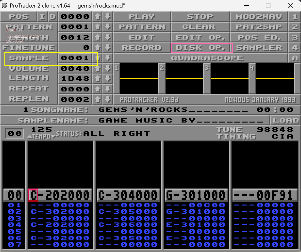 Goto Disk OP and load your Modul File 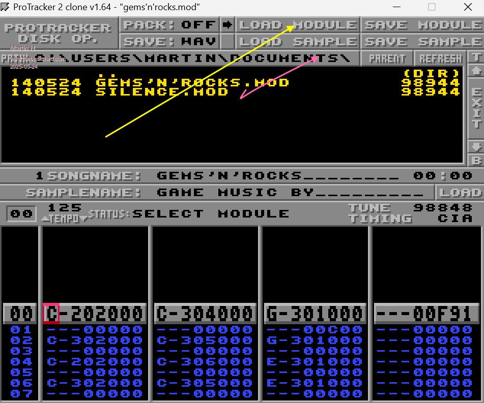 Click on the Sampler Button and change the Samplenumber to chouse a empty slot 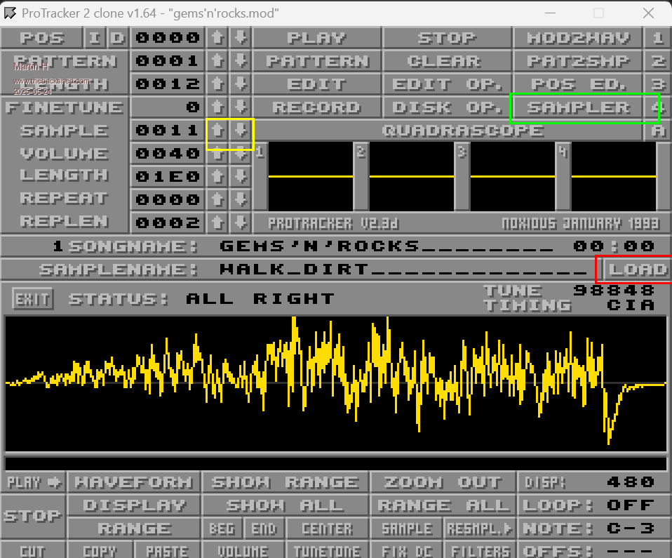 Then just load your Sample at this slot, close the Sampler and Save the MOD File. Now your mmbasic Program can play the Sample with the PLAY MODSAMPLE Samplenum, channel. Samplenum is the number of the slot into which you have loaded your sample, channel (1 to 4) You can choose this freely between 1 and 4, I would “rotate” the number to make sure that the channel is not already being used by another SFX. Edited 2025-05-24 20:50 by Martin H. 'no comment |
||||
| dddns Guru Joined: 20/09/2024 Location: GermanyPosts: 875 |
Many thanks for that howto! In Ubuntu22 its even included |
||||
| Volhout Guru Joined: 05/03/2018 Location: NetherlandsPosts: 5994 |
@Martin.H Yes, I am getting the hang of it. For this you only need to touch the surface of this capable tool. Composing your own songs is the complex part. Adding SFX to a MOD song is super simple.... Thanks for giving me a push in the right direction. Volhout Edited 2025-05-24 23:28 by Volhout PicomiteVGA PETSCII ROBOTS |
||||
| Martin H. Guru Joined: 04/06/2022 Location: GermanyPosts: 1485 |
Volhout, yes I've done the song for GemsnRocks by myself.. First made in my DAW (FL Studio) and later transfered it Note by Note to the Mod Format.Unfortunately, there are no ready-made tools for this, as the formats are totally different. As described, I have a musical background and still remember the time at the beginning of the 90s with the Noisetracker, so the type of operation is not quite so unusual. The programs come from a time before Windows, when everyone made their own GUI. 'no comment |
||||
| g0730n Newbie Joined: 14/05/2025 Location: United StatesPosts: 18 |
I feel like learning creating MOD files with the tracker will be more difficult for me then building the picomite and learning MMBasic lol... but i do want to eventually create and use all my own SFX and music. So for now just using opengame art sounds and music as placeholders. |
||||
| Marcel27 Senior Member Joined: 13/08/2024 Location: NetherlandsPosts: 104 |
Nice work! |
||||
| Martin H. Guru Joined: 04/06/2022 Location: GermanyPosts: 1485 |
I have found an entertaining little introduction to working with MOD files. Making electronic dance music in 1990 with budget home computer perhaps it will help to better understand some things and how to use trackers. Cheers Martin 'no comment |
||||
| The Back Shed's forum code is written, and hosted, in Australia. | © JAQ Software 2026 |
