
|
|
Forum Index : Microcontroller and PC projects : Stripboard PicoMite
| Author | Message | ||||
| Mixtel90 Guru Joined: 05/10/2019 Location: United KingdomPosts: 8965 |
Just my take on a design. This one fits the RM2015S case from Hammond, so it can look rather nice (and even dust-free!). This case can be found for about £3.79 + postage here in the UK (Rapid Electronics). so it's probably hardly worth 3D printing one. This hasn't been easy to test on SL6, but it does seem to work ok if I swap the strips for normal traces and put the links on proper trace layers. Note, this uses the Adafruit module for the HDMI connector as there's no other realistic alternative. If you intend to build this get that first. It also uses the "inverted" micro SD card module as that fits the track layout better than most. You may be able to find this without the pins ready soldered, in which case fit them from the socket side. info.pdf circuit.pdf 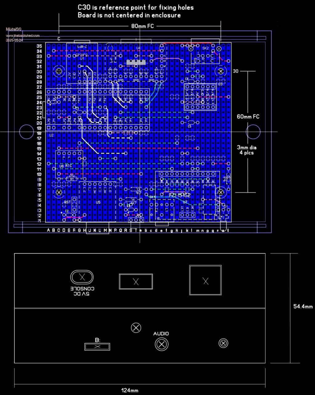 Mick Zilog Inside! nascom.info for Nascom & Gemini Preliminary MMBasic docs & my PCB designs |
||||
| dddns Guru Joined: 20/09/2024 Location: GermanyPosts: 875 |
Hello Mick, I think this is an excellent idea and ideal for tinkers and newcomers to get a start. What would you think: I never cut a cheap HDMI cable and simply use a standard 2,54mm socket / header or even solder the wires directly to the board. Of cause not so nice but almost priceless and that would be my reason.. Adafruit is hard to get and twice the price of a Pico2 I can't effort.. I admit that reason might be irrelevant for the most, so just a suggestion. Have you got a solution, how to cut the traces best? And the cuts are hard to see in the drawing, could you mark them e.g. in red? Nice work! |
||||
| Mixtel90 Guru Joined: 05/10/2019 Location: United KingdomPosts: 8965 |
You could probably use a piece of stripboard with the resistors mounted on it to connect a HDMI cable. It might be a bit messy but it should work. TBH, even if the Adafruit module is a bit on the expensive side I'd use it. After all, everything else is pretty cheap! Colouring in SL6 is fun. You have colours for the outline, copper and silkscreen layers. Then there are two internal copper layers. If you attempt to use those as non-conducting layers things all fall to pieces! Working with stripboard For cutting traces I've used two methods. A normal drill bit (which works but hurts your fingers after a while) or a proper "spot face cutter" tool. I strongly recommend getting one of those. They are well worth it and last for years. The little between-hole cuts under the PS2 socket need to be done using a craft knife. I make two cuts close together then peel the strip out. You can also use a craft knife to help you peel lengths out of a strip if you want electrical clearances. You can cut the board by scoring it with the knife on both sides, along some holes, then snap it. Clean the board up with a file after. Always allow for the holes that you'll be cutting through! It's very, very annoying to discover that your nice, cleaned up board is one strip short.... :( Mick Zilog Inside! nascom.info for Nascom & Gemini Preliminary MMBasic docs & my PCB designs |
||||
| Mixtel90 Guru Joined: 05/10/2019 Location: United KingdomPosts: 8965 |
This might help. It's a view of the copper side of the board with most of the other stuff removed. You really need the other picture too. 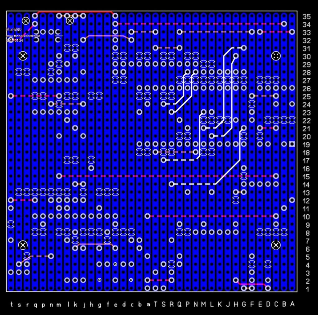 Mick Zilog Inside! nascom.info for Nascom & Gemini Preliminary MMBasic docs & my PCB designs |
||||
| phil99 Guru Joined: 11/02/2018 Location: AustraliaPosts: 3322 |
Those are the same methods I have been using also. A drill holder is the solution. It can be as simple as one segment cut off a two-screw terminal strip. Choose one with a 3mm (or a little bigger) cable hole to fit the drill. For the deluxe version remove the two screws and press the tunnel out of the plastic. Then get a file handle or short piece of fat dowel (eg broom handle), drill a hole in the end just big enough for the tunnel and two holes in the side for the screws to reach their screw holes. This makes it much easier. |
||||
| Peter63 Senior Member Joined: 28/07/2017 Location: SwedenPosts: 199 |
Hello This is how I built my own HDMI version some time ago. Maybe you can get some ideas for your own building. Case is G738 from Velleman 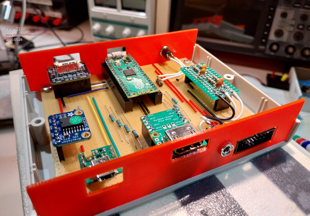 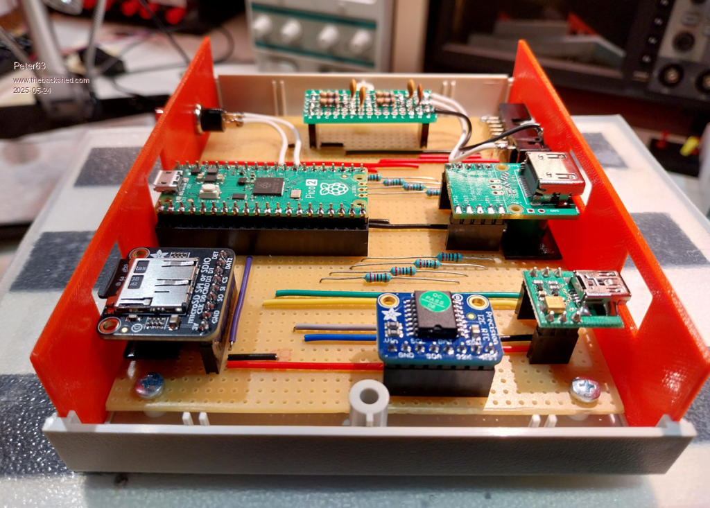 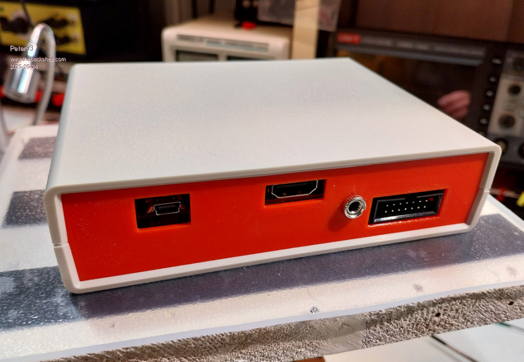 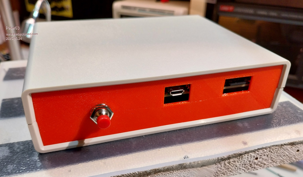 /Peter63 |
||||
| Mixtel90 Guru Joined: 05/10/2019 Location: United KingdomPosts: 8965 |
Very nice, Peter, and very red! :) It looks like you might have used pad board? I was being deliberately awkward and restricting myself to a relatively easily available size of ordinary stripboard and the cheapest decent enclosure I could get. It was just for the challenge. :) Phil: I'll remember that when my spot face cutter wears out in another ten years (at this rate - don't hold your breath!). Everyone: Adafruit DVI breakout modules seem to be available again. The Pi Hut have them for £1.95 inc VAT, plus postage. They will be available from other maker-type suppliers no doubt. Mick Zilog Inside! nascom.info for Nascom & Gemini Preliminary MMBasic docs & my PCB designs |
||||
| stanleyella Guru Joined: 25/06/2022 Location: United KingdomPosts: 2807 |
hdmi to strip board is always my prob. I used the board with the resistors surface mounted but dunno what you're using |
||||
| dddns Guru Joined: 20/09/2024 Location: GermanyPosts: 875 |
Very nice and clean build! If you do it like this, it will run as stable as a manufactured pcb.. @Mick I can't find one german seller below 9€..better said there is only one :)) I'll try a self made connection with a standard tub connector and will report |
||||
| Mixtel90 Guru Joined: 05/10/2019 Location: United KingdomPosts: 8965 |
I have a design that replaces the Adafruit board but there are problems: It is "longer" (i.e. back of board to row of pins) by 0.1in. It is all SMD, with 0805 resistors. The HDMI connector is a bit of a pig to solder. JLCPCB will happily send you 5 boards. There are 12 breakouts per board, so you have 59 to get rid of. :) It may well end up costing you as much as it does to pay the 9€. Mick Zilog Inside! nascom.info for Nascom & Gemini Preliminary MMBasic docs & my PCB designs |
||||
| dddns Guru Joined: 20/09/2024 Location: GermanyPosts: 875 |
Maybe make a business :)) |
||||
| Mixtel90 Guru Joined: 05/10/2019 Location: United KingdomPosts: 8965 |
I did consider it. It might at least buy me a little hot plate for soldering all those resistors! :) Mick Zilog Inside! nascom.info for Nascom & Gemini Preliminary MMBasic docs & my PCB designs |
||||
| dddns Guru Joined: 20/09/2024 Location: GermanyPosts: 875 |
I would try! I'm not into it: if you would use it for a 5V system, would the resistors be same sized or even will they be necessary in any way and setup? maybe an idea: sell it as tinker set with a set of resistors(with R0 too) Edited 2025-05-25 08:40 by dddns |
||||
| Peter63 Senior Member Joined: 28/07/2017 Location: SwedenPosts: 199 |
I took some photos from underneath, where you can see that I used a nice knife to break the tracks. Using stripboard reduces the amount of wiring. 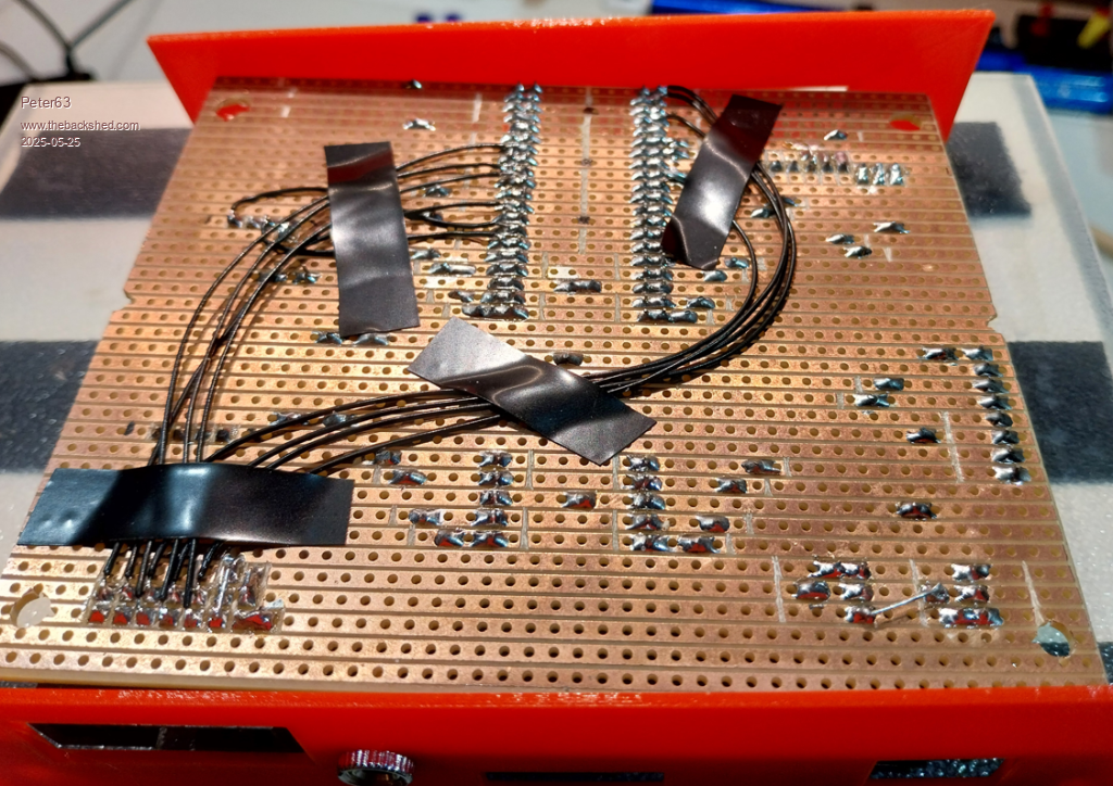 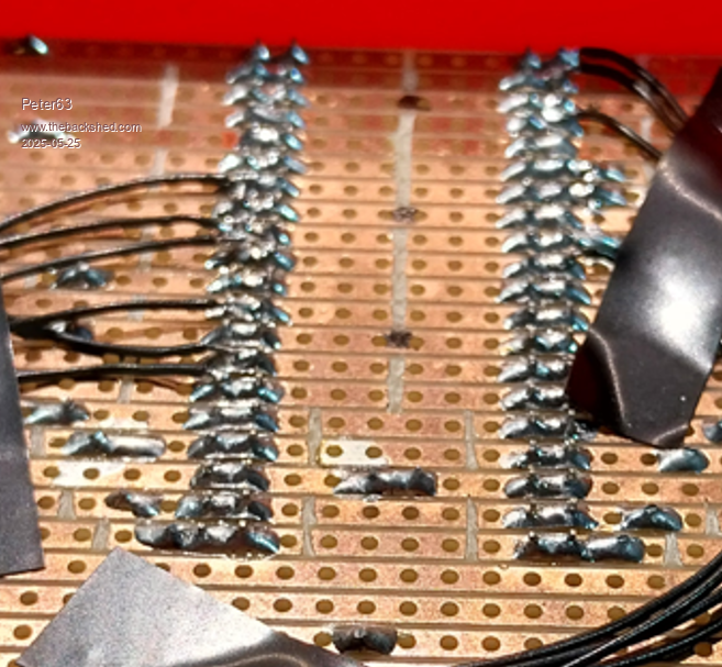 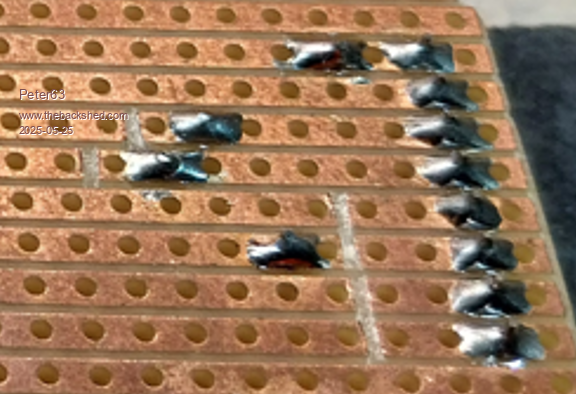 Using stripboard from https://www.electrokit.com 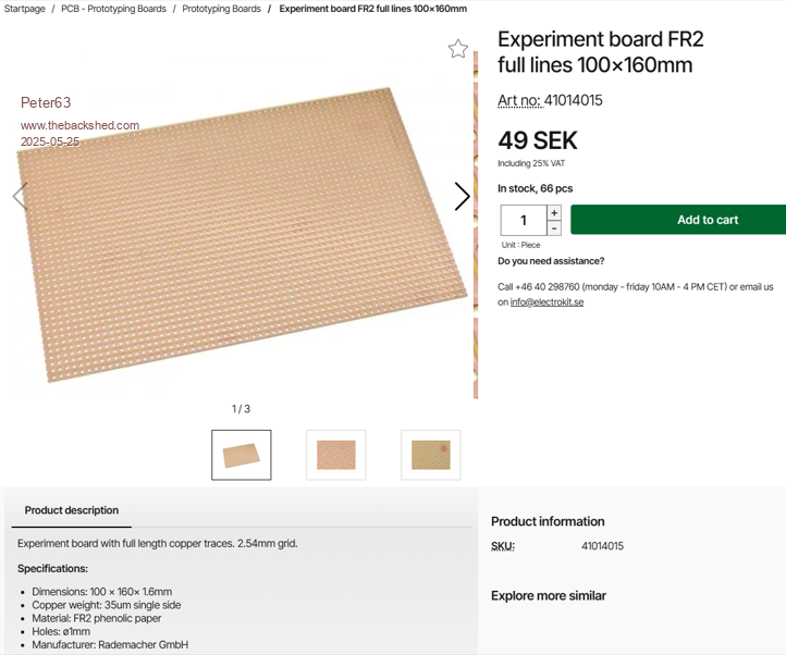 |
||||
| Peter63 Senior Member Joined: 28/07/2017 Location: SwedenPosts: 199 |
I use DVI Sock from electrokit 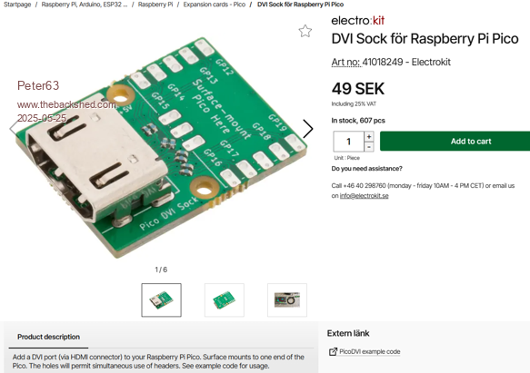 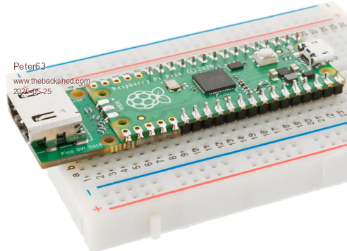 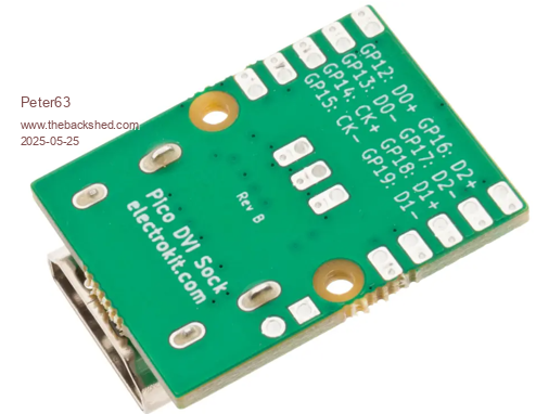 /Peter63 |
||||
| dddns Guru Joined: 20/09/2024 Location: GermanyPosts: 875 |
Superb build! I could order @electrokit but way too expensive with 5€ for the socket and 10 for shipping. I've seen this long ago but now disappeared from market.. but very nice with the option to solder it directly. So if I ever want to see HDMI there is no other option for me than to cut a used cable from trash and solder the wires directly.. Anyone tried, does HDMI output work as well with the 2350B? HSTX pins are same pinout as least.. |
||||
| Mixtel90 Guru Joined: 05/10/2019 Location: United KingdomPosts: 8965 |
The DVI Sock and the HSTX are fully compatible AFAIK. The system was deliberately designed like that. The "accepted standard" DVI pins for the RP2040 were simply copied over when the HSTX was being created. They are more expensive than the Adafruit module though. Mick Zilog Inside! nascom.info for Nascom & Gemini Preliminary MMBasic docs & my PCB designs |
||||
| The Back Shed's forum code is written, and hosted, in Australia. | © JAQ Software 2026 |
