
|
|
Forum Index : Microcontroller and PC projects : Counting pulses, while the MM sleeps....
| Author | Message | ||||
| Mixtel90 Guru Joined: 05/10/2019 Location: United KingdomPosts: 8965 |
This sort of charger and cell protection stuff is fine for what it's intended to do - charge a cell for something, cut the charge off when the cell voltage is sensible and disconnect the load when you are getting to the lowest safe voltage for the cell. It's not intended for cell capacity monitoring and it doesn't care about it. Even the "charge me now" point doesn't need to be precise, it's just a warning. All happening at a room temperature of about 20C. Take this system outside it's design boundaries and it's actually a bit rough! It takes a lot more to handle cell capacity measurements as used on EVs. Unfortunately that's the only way you can approach accuracy. My favourite approach is to charge two cells from two chargers. The load is on one of them until the terminal voltage drops to a preset point. The second cell then takes over, the original is locked out so it's recovering terminal voltage won't bring it into play again. A signal is given to trigger the charging process for both cells or bring up a low battery alarm. That gives time for the system to be handled. The second cell doesn't double the load time of the system, that's regarded as being ended at the cell changeover point. The second cell doesn't need the same capacity as the main one but if the warning is ignored the system will die when it runs flat. It's rather like the "standby fuel tank" that some cars used to have (they may still do - I know nothing about cars!). Mick Zilog Inside! nascom.info for Nascom & Gemini Preliminary MMBasic docs & my PCB designs |
||||
| phil99 Guru Joined: 11/02/2018 Location: AustraliaPosts: 3321 |
Here is a MM2 tested program for monitoring the tilt switch and Li-ion cell. It can read the cell volts up to 4.1V with the divider values shown in the diagram. If you only need up to 3.3V the lower leg can be removed. The current through the upper leg of the divider doesn't get wasted while the MM2 is sleeping. The lower leg of the divider gets switched off and the diode diverts the current to the 3.3V rail, helping power the MM2. When the cell volts are less than 3.4V no current will flow through it anyway. ' "Test cell V & tilt.bas" Print "Time",,"count","Cell V",,"Tilt" Do SetPin 25, DOUT, OC 'switch for voltage divider lower leg Pin(25) = 0 SetPin 24, AIN 'Cell Volts SetPin 21, DIN, Pullup 'Tilt switch input SetPin 22, DOUT, OC 'Tilt switch simulator, link to pin 21. Delete if real tilt sw. used Pin(22) = 1 If (n Mod 5)=4 Then Pin(22)=0 'activate simulated tilt switch ' Pause 10 'Allow time for capacitor on AIN to settle. If cap. isn't used remove this RTC gettime 'optional Print Time$, n, Pin(24)*(390+100)/390, Not Pin(21) 'insert your voltage divider values here SetPin 24, off SetPin 25, off SetPin 21, off SetPin 22, off n=n+1 'n = loop counter - optional If n > 19 Then End 'remove this for continuous running CPU sleep 5 Loop 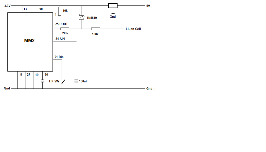 > RUN Time count Cell V Tilt 01:37:18 0 4.10765 0 01:37:23 1 4.12724 0 01:37:27 2 3.99417 0 01:37:32 3 3.96918 0 01:37:37 4 3.81719 1 01:37:42 5 3.74221 0 01:37:46 6 3.64764 0 01:37:51 7 3.44229 0 01:37:56 8 3.33219 0 01:38:01 9 3.25045 1 01:38:06 10 3.05997 0 01:38:10 11 2.85259 0 01:38:15 12 2.68441 0 01:38:20 13 2.16494 0 01:38:25 14 1.79613 1 01:38:30 15 1.41112 0 01:38:34 16 1.19629 0 01:38:39 17 0.880838 0 01:38:44 18 0.426234 0 01:38:49 19 0.263979 1 > Edited 2025-10-05 20:05 by phil99 Footnote added 2025-10-06 08:58 by phil99 In the circuit above the 5V to 3.3V regulator is a switch-mode type which is why I added the capacitor on the AIN pin (and Pause in the program). I assumed that noise would be an issue (similar to the cell-to-5V converter in Grogster's setup), however removing the capacitor and Pause make little difference. The noise is fairly low at about 20mV. |
||||
| vegipete Guru Joined: 29/01/2013 Location: CanadaPosts: 1182 |
The pins likely won't change during the read, but that's not the issue. It _is_ quite likely that the read will happen during the count. But thinking further, all this is excessive. It's a measurement of a very slowly changing signal - battery voltage. The MicroMite need only count the LED pulses every few minutes or even tens of minutes. When it's time to count pulses, stay awake for the few seconds required to catch a long pause, the pulse count and the next long pause. Many minutes later, a longer wake period can count pulses again. Visit Vegipete's *Mite Library for cool programs. |
||||
| Mixtel90 Guru Joined: 05/10/2019 Location: United KingdomPosts: 8965 |
As Jim said, it's no problem. Read several times with a little delay between them. Get best out of 3 or something, or keep reading with delays until you get two or more readings that agree, The system will be telling you lies anyway. ;) If the battery is completely dead you will get a zero, undetectable, count after a zero, undetectable, 1000ms delay... Or, as I said a while ago, freeze the count while you read. The read gate will be open for the length of the monostable time, which started on the leading edge of the first bit of the count. Vilhout's counter was even cleverer. :) Although the idea is to synchronise the 5s and 1s delays it can't be done. The 1s delay *has* to trigger the 5s delay. It can't work the other way as the MM2 has no control over the charger. Because of this the MM2 *will* wake every 1s, not every 5s, even if it does nothing and goes back to sleep immediately. It may as well read a hardware counter and store the value then process 5 readings every 5s. Mick Zilog Inside! nascom.info for Nascom & Gemini Preliminary MMBasic docs & my PCB designs |
||||
| phil99 Guru Joined: 11/02/2018 Location: AustraliaPosts: 3321 |
That will be an added drain on the cell, which Grogster wants to avoid. In the circuit above (tested and working) the cell is read directly via a voltage divider (BigMik's suggestion) so timing issues don't occur. It doesn't draw any extra current while the MM2 sleeps. As it monitors the cell directly Grogster can set whatever low battery alarm he wants, while the flashing led levels are not specified in the data sheet. They could be too high or low to ensure the maximum time between recharges without risk of going flat. . Edited 2025-10-06 09:13 by phil99 |
||||
Grogster Admin Group Joined: 31/12/2012 Location: New ZealandPosts: 9995 |
Hello folks.  Still here, still reading all the posts. To be frank, I did not think this question would generate so much discussion!  I'm happy that it DID, but I was only expecting a couple of replies, not three pages!  Having said that, and with all that is being discussed, I think I do rather like the idea of just measuring the voltage on the cell. I did not think I could do that accurately, as Li-ION cells don't have to vary that much in their terminal voltage between "Good" and "Flat", if you see what I mean, so the window of measurement has to be quite strict, and I was not sure if the MM2's ADC was up to the job. It seems that it is based on phil99's experiments. The LDR idea was also genius - never even CONSIDERED that concept, and it is so simple! Volhout, my hat tips to you, sir.  I do some more re-reading of the posts here, and get back to the thread soon. Smoke makes things work. When the smoke gets out, it stops! |
||||
| Mixtel90 Guru Joined: 05/10/2019 Location: United KingdomPosts: 8965 |
There are many ways to skin some cats. :) Luckily the MM2 has a better ADC than the original RP2040. Mick Zilog Inside! nascom.info for Nascom & Gemini Preliminary MMBasic docs & my PCB designs |
||||
| zeitfest Guru Joined: 31/07/2019 Location: AustraliaPosts: 692 |
Some tilt sensors used a blob of mercury in a glass tube and could handle robust currents. Maybe just power the MM bit via the tilt sensor and let it run free |
||||
| Mixtel90 Guru Joined: 05/10/2019 Location: United KingdomPosts: 8965 |
Tilt sensor triggers a thyristor. That turns on the supply to the MM2. That does its stuff then raises the base of a transistor that shorts out the thyristor. It then drops that output and consequently switches itself off until next time. :) Why do it the easy way when you can make it complicated? ;) Mick Zilog Inside! nascom.info for Nascom & Gemini Preliminary MMBasic docs & my PCB designs |
||||
| The Back Shed's forum code is written, and hosted, in Australia. | © JAQ Software 2026 |
