
|
|
Forum Index : Microcontroller and PC projects : solid state audio filter for picomite PWM output, JLC basic
| Author | Message | ||||
| Volhout Guru Joined: 05/03/2018 Location: NetherlandsPosts: 5994 |
Hi Peter, This is the audio filter (similar to pico buddy) tailored to use JLC basic components. The JLC part numbers are added. The only part that is not JLC is the opamp. You can use MCP6002 for mono, and 2 MCP6002 for stereo, or a single MCP6004. In case PAM8302 (mono 2W) you couple the 2 PWM outputs through R5 and R8 to 1 audio filter. In case PAM8406 (stereo 5W) you have to build 2 filters, one for each L and R. 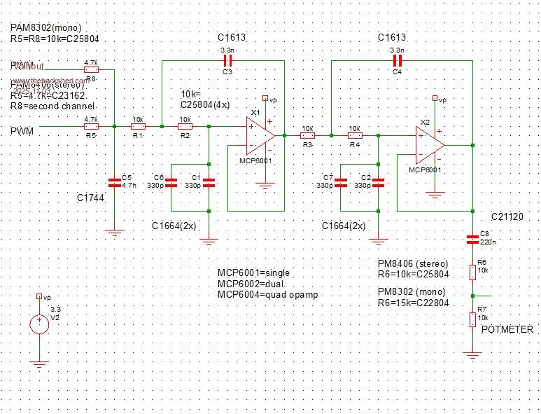 Regards, Volhout P.S. the picobuddy used a diode clamp between PWM and the input of the active filter. That diode clamp improves the power rail noise immunity (noise from the pico switcher). But when using a linear 3V3 power supply that may not give any improvement. P.P.S. I did not prototype this circuit. Pure simulation. If you need me to, then I'll have to order parts first. But in essence it is (values changes) same as the picobuddy circuit. Edited 2025-11-03 22:19 by Volhout PicomiteVGA PETSCII ROBOTS |
||||
| matherp Guru Joined: 11/12/2012 Location: United KingdomPosts: 11642 |
That's great. I'll prototype it in the next couple of days. Have you had a look at my VGA from Basic ? Quite pleased with this and have now got a RGB TFT running off it. Just load standard PicoMite onto a rp2350 and stick it in the VGA DESIGN 2 board to run it. |
||||
| matherp Guru Joined: 11/12/2012 Location: United KingdomPosts: 11642 |
Harm, just been though my parts store and only have MCP602 in stock. OK to test with this? |
||||
| Mixtel90 Guru Joined: 05/10/2019 Location: United KingdomPosts: 8965 |
Looks like it should work. Comparison part way down the page Mick Zilog Inside! nascom.info for Nascom & Gemini Preliminary MMBasic docs & my PCB designs |
||||
| Volhout Guru Joined: 05/03/2018 Location: NetherlandsPosts: 5994 |
@Peter, The MCP602 does not have rail-rail inputs. If just for prototyping, you can use it but power it from +5V, +4.5V (Vsys), but not 3V3. Then it will work. But there are alternate opamps that may also work. Give me a moment, I will check. Manufacturer Dual Quad TI LMV922 LMV924 (older part) TI TLV9102 TLV9104 ST TS952 TS954 ST TS922 TS924 AD AD8542 AD8544 TI OPA2342 OPA4342 If you find other parts that can run of 3.3V and are RRIO (rail to rail Input and Output) they most likely work if their GBW (Gain Bandwidth product) is 1MHz or higher. Volhout Edited 2025-11-04 00:39 by Volhout PicomiteVGA PETSCII ROBOTS |
||||
| Volhout Guru Joined: 05/03/2018 Location: NetherlandsPosts: 5994 |
@Peter, When you are adventurous, and want to go for really low cost... This is the discrete version of the filter. Taking benefit of the fact that the PAMxxxx amplifiers do not need full 3.3V swing at their input. We attenuate 2x in each stage, allowing the transistor bias voltage, and maximum output swing at their collector. Powered from 3.3V... 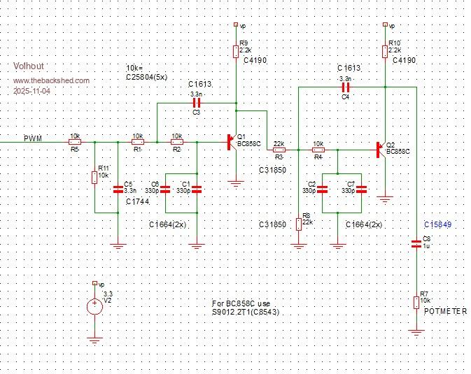 Volhout PicomiteVGA PETSCII ROBOTS |
||||
| DaveC5 Newbie Joined: 24/09/2025 Location: United KingdomPosts: 40 |
Hi, hope you don't mind me jumping in, The other thing the diode and resistor arrangement on the op-amp input does is limit the PWM from the Pico to less than 1Vpkpk centred around Vsupply/2. You trade the full 3.3Vpkpk swing from the Pico for a smaller one, but it does mean you're not restricted to using rail-rail parts in the filter op-amp. You could perhaps then restore the full voltage swing by setting the PAM input amplifier gain accordingly. 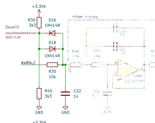 |
||||
| The Back Shed's forum code is written, and hosted, in Australia. | © JAQ Software 2026 |
