
|
|
Forum Index : Microcontroller and PC projects : New board for robot
| Author | Message | ||||
| karlelch Guru Joined: 30/10/2014 Location: GermanyPosts: 335 |
I used the core of Peter's circuit design (Picomite HDMI v1.3, thanks @Peter!) for a new robot control board. Converted the EasyEDA files to KiCad and added circuitry for motor, LCD etc. control. PCBway did not want to produce it, because the pads of the RP2350 footprint were too close (?) - JLCPCB had no problem with that and the board works nicely  Interesting experience ... Interesting experience ...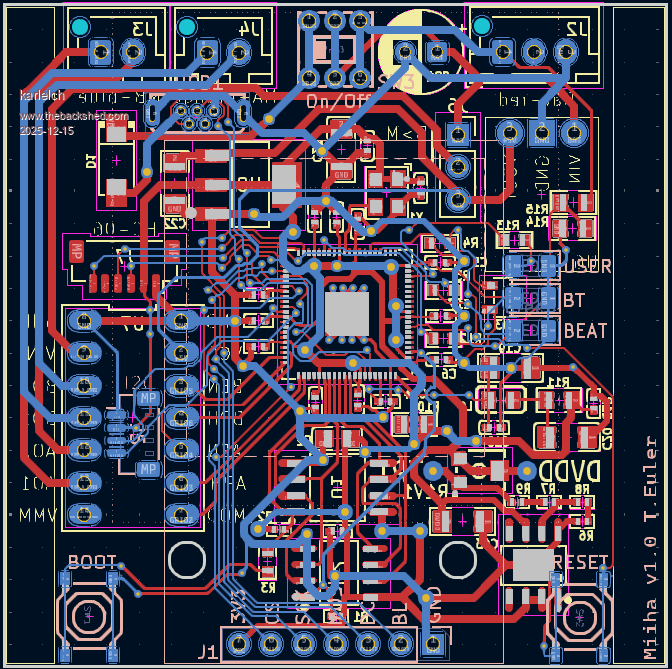 |
||||
| karlelch Guru Joined: 30/10/2014 Location: GermanyPosts: 335 |
Incidently, I recently got my hands on a robot kit (Miika). It's a bit too expensive to by it from the original company, but it is well made and the mechanics is nice - two motors turn and walk the robot in any direction. The idea is that you train an AI on your cellphone such that you can make gestures to your phone to steer the robot. I thought that is is a bit silly and that the nice kit needs MMBasic ... The original board (pictures below, right) has an ESP32, and LED matrix and a buzzer, as well as connectors for two motors. No options for adding sensors and such. My redesigned board (left) allows to connect two motors, I2C devices (sensors), and a Bluetooth breakout. I also added a 240x240 TFT display, a few LEDs and a USB connector. All controlled by an RP2350 (using Peter's core design). As soon as I tested all components, I'll continue building the robot and then the software ... Front: 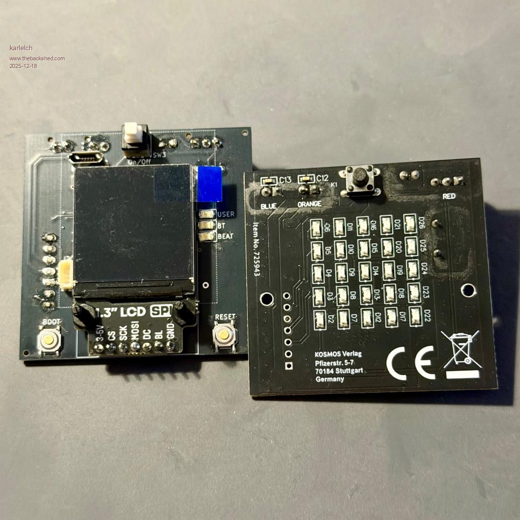 Back: 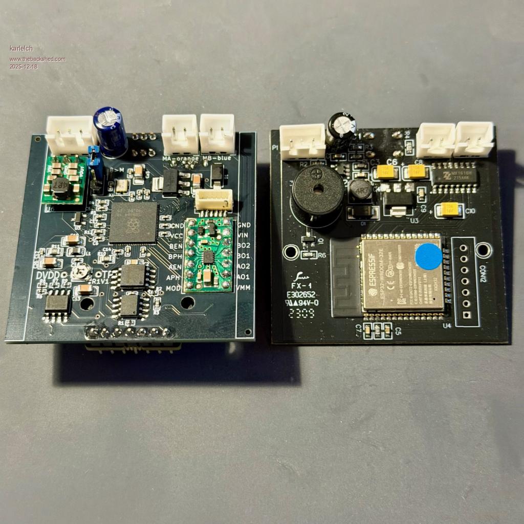 Here is the new board sticking in one half of the robot: 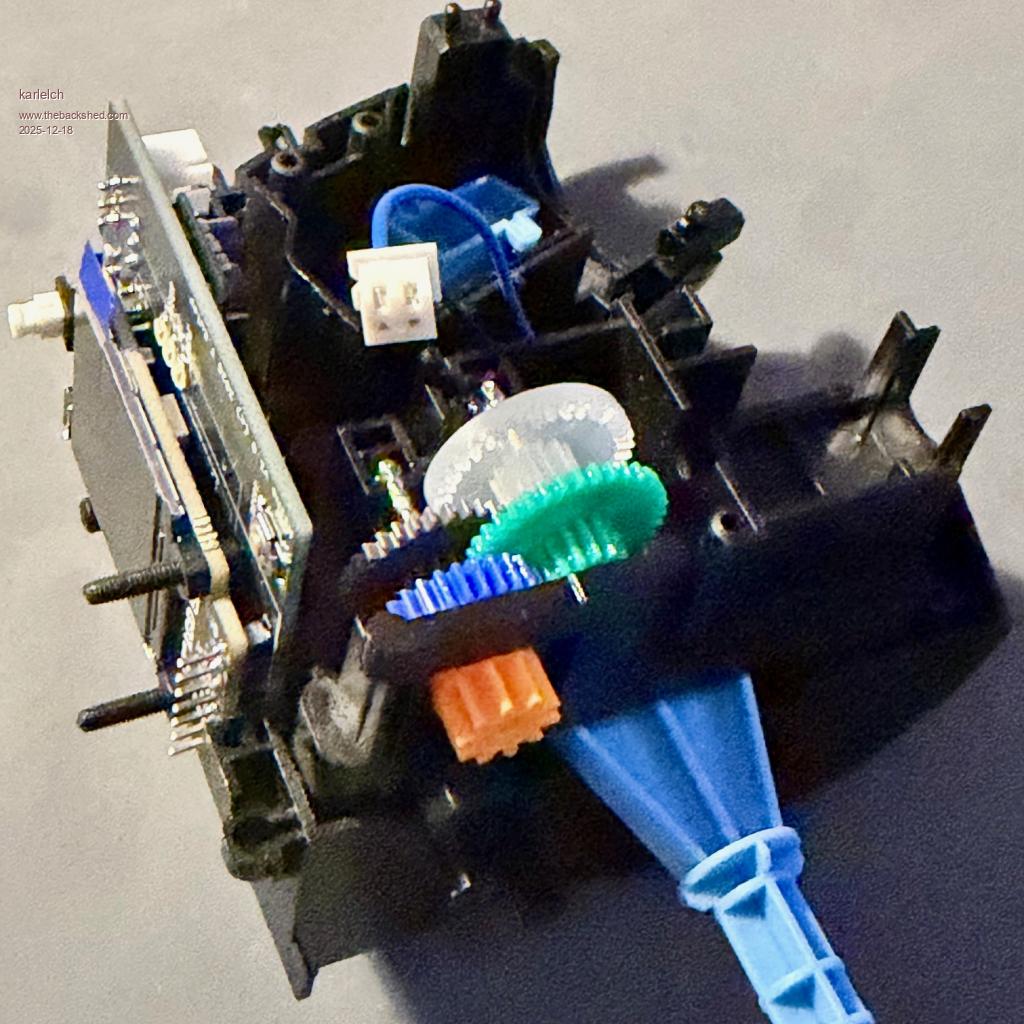 |
||||
| karlelch Guru Joined: 30/10/2014 Location: GermanyPosts: 335 |
After testing the board (and finding only minor issues), I assembled the robot and wrote a first version of the software - currently only remote controlled - using the latest experimental firmware with good use of structures. I will document this soon on GitHub. Here are two videos as preview. The first one shows the robot powering up, walking a bit and shutting down. The second one shows the robot trying to hit the camera ... (if the program throws an error, the motors are sometimes not turned off ...) Cheers Thomas |
||||
| PhenixRising Guru Joined: 07/11/2023 Location: United KingdomPosts: 2005 |
Very cool  Honestly, the combined power of the PicoMite and a mobile device is immense. |
||||
| Amnesie Guru Joined: 30/06/2020 Location: GermanyPosts: 763 |
Woah! This is insane! Watched the videos  Cute robot and nice power off animation with that eye. Cute robot and nice power off animation with that eye.Edited 2025-12-30 09:34 by Amnesie |
||||
| The Back Shed's forum code is written, and hosted, in Australia. | © JAQ Software 2026 |
