
|
|
Forum Index : Microcontroller and PC projects : controlling 6 LCD displays with 1 PicoMite
| Author | Message | ||||
| mozzie Guru Joined: 15/06/2020 Location: AustraliaPosts: 403 |
G'day Gerald, A novel approach and a brilliant looking setup. You might like to try cutting up the grey anti-static bag into strips as a filter for the WS2812 LEDs, several layers may be required. Works very well on overly bright power LEDs on all sorts of things here  Regards, Lyle. |
||||
| ville56 Guru Joined: 08/06/2022 Location: AustriaPosts: 550 |
Thanks for the tip Lyle. Will give it a try. Should have some of the bags somewhere. 73 de OE1HGA, Gerald |
||||
| ville56 Guru Joined: 08/06/2022 Location: AustriaPosts: 550 |
attached is the circuit diagram for the display unit as I've built it. 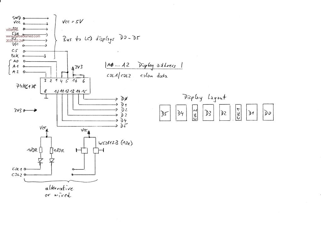 the signal names partial buried under the watermark are: GND Ground Vcc 5V SCL serial clock SDA serial data RS reset D/C data/command CS chip select BLK backlight control I left RS bus wire floating without any issues so far, it must not (sic !) be connected to the pico if the standard MMBasic "gui reset lcdpanel" init is used for each LCD position. I'am currently reading thru the ST7789 datasheet to find out how to init the displays with poke display commands. Should be a lot faster and seems to be feasable. For the colons the LED and the WS2812B are interchangeable in my design. On the software side I still have to do a lot of improvements, so I will post the code in a few days at the earliest. I have a lot of grandpa duties as well  and a doughter-in-law in the wheelchair .... and a doughter-in-law in the wheelchair ....73 de OE1HGA, Gerald |
||||
| v.lenzer Senior Member Joined: 04/05/2024 Location: GermanyPosts: 123 |
Hi Gerald! I'm fascinated by the small displays and wanted to try building a Wi-Fi kitchen clock before replicating your Nixie project. Unfortunately, I haven't been able to get the display to work yet. IF YOU HAVE THE TIME, would it be possible for you to post the options and connection pins for the pico-W with RP2040? Best wishes! Joachim |
||||
| ville56 Guru Joined: 08/06/2022 Location: AustriaPosts: 550 |
Joachim, here you go: my options: WebMite MMBasic RP2350A Edition V6.02.01RC5 OPTION SYSTEM SPI GP2,GP3,GP4 OPTION SYSTEM I2C GP8,GP9 OPTION FLASH SIZE 4194304 OPTION COLOURCODE ON OPTION HEARTBEAT OFF OPTION CPUSPEED (KHz) 252000 OPTION DISPLAY 40, 145 OPTION LCDPANEL ST7789_320, PORTRAIT,GP14,GP13,GP15,GP16 OPTION TELNET CONSOLE ON OPTION SDCARD GP17 the pin usage is documented here: Clock-Pinout.pdf you can check the function of the displays easily just by connecting one display to the SPI pins. A simple BOX, LINE or TEXT command should proof the function. But be aware of the offset for the x-axis with 35. If you want I can also post my current code here. It should be easily adaptable to whatever pin usage you choose. But, like all of my code, it is rather overdone  for just serving as a clock as I also did some coding experiments for extended parametrization and debugging capabilities. for just serving as a clock as I also did some coding experiments for extended parametrization and debugging capabilities.BTW: I had the code running not only on the WebMite but also on other types of RP2350 processors. The WebMite is my final solution because I use NTP to synch the date/time. But it can also run with a RTC module or even on the processor xtal alone if you want and don't care about the drift. DCF decoding is still not implemented. 73 de OE1HGA, Gerald |
||||
| v.lenzer Senior Member Joined: 04/05/2024 Location: GermanyPosts: 123 |
Hello Gerald! Thank you very much for answering so quickly and in detail! I hope, I will have success. As I see, You are connecting GP10 to 15 with the LCD , but in the options for the LCDpanel You are using GP14 to 16. Is this ok? Edited 2026-03-15 10:18 by v.lenzer Best wishes! Joachim |
||||
| v.lenzer Senior Member Joined: 04/05/2024 Location: GermanyPosts: 123 |
Hello Gerald! It's working!! I just changed to OPTION SYSTEM SPI GP10,GP11,GP12 Thank You once again! Best wishes! Joachim |
||||
| ville56 Guru Joined: 08/06/2022 Location: AustriaPosts: 550 |
sorry Joachim, my bad, misleading information. The initial idea was to have a seperate SPI bus for the lcd panels but it turned out this is not possibe with ST7789. My fear was the length of the bus wiring, more than 30 cm, and the load with 6 panels would not work reliably, if at all, and so some HW tricks could be necessary. But it does, even with an SD card connected at the end of the bus. And this lcd SPI pins where still allocated in the docu. I use GP2,3,4 for system spi and GP13,14,15,16 for the rest of the lcd panel signals. GP10,11,12 are not allocated so far. 73 de OE1HGA, Gerald |
||||
| v.lenzer Senior Member Joined: 04/05/2024 Location: GermanyPosts: 123 |
Hi Gerald! That's absolutely fine. I'm just glad I made any progress at all. I've left my settings as they are. It's a completely different project than the "Nixie" anyway. Best wishes! Joachim |
||||
| ville56 Guru Joined: 08/06/2022 Location: AustriaPosts: 550 |
Joachim, maybe it is of interest for you: there are, at least, 2 different methods to init the individual ST7789 LCD panels. 1) is the easy way, but slow 'secure reset sequence gui reset lcdpanel 'perform reset on this display position cls 'remove garbage 2) is the faster way, I figured out by reading through the datasheet 'fast reset sequence, for details see ST7789 datasheet poke display &h01 'swreset (soft reset) poke display &h11 'slpout (exit sleep mode) pause 120 'this pause is needed poke display &h13 'noron, set normal display mode on poke display &h36, &hC0 'MADCTL, to flip hor and vert sides poke display &h3a, &H55 'colmod, 16 bit/px Pause 10 'next needed pause poke display &h21 'invon, invert colors if lcd_gamma <> 1 then poke display &h26, lcd_gamma 'set display gamma value poke display &h29 'dispon, turn display on cls - the pause statements could be replaced by polling the panel status, but I was too lazy for that - the lcd_gamma value can be 1,2,4 or 8 and changes the gamme of the display (what a surprise  ). Can be useful to enhance the readability of the display, depends on the quality of the picture data. ). Can be useful to enhance the readability of the display, depends on the quality of the picture data.- With the MADCTL command you can setup any orientation you like. But it should be the same as in the options lcdpanel, otherwise positioning may not work as expected. Mine are OPTION LCDPANEL ST7789_320, PORTRAIT, pins ... for the example above. - INVON may be needed, depending on the display type (TFT or IPS) all in all the sequence with the pokes is about 2 to 3 times as fast as the init with gui reset lcdpanel. If you have to init 6 displays in sequence, this is quite a lot faster. The code and the options are for the 170x320 displays that can be bought from several sources for a few bucks. If you can manage to assert all CS signals in parallel at the same time to the displays I think only one init sequence should be sufficient as there are no input data from the display to the pico. So they just listen to their master. For the individual control individual CS signals are then again necessary. Some additional hardware in excess to the 1:8 demux IC would be needed. E.g. 7 gates ( 6 EXOR for the CS and one of the 4 free outputs from the demux with an inverting EXOR). 73 de OE1HGA, Gerald |
||||
| v.lenzer Senior Member Joined: 04/05/2024 Location: GermanyPosts: 123 |
Hi Gerald! You've really delved into this in depth. It's certainly not necessary for my Wi-Fi kitchen clock. But it is for multiplexing the displays. At the moment, I'm only using OPTION SYSTEM SPI GP10, GP11, GP12 OPTION LCDPANEL ST7789_320, LANDSCAPE, GP14, GP13, GP15, GP16 and in the program, only CLS and TEXT... I'm thrilled with these displays. They're just the right size for a clock or measuring instrument display and, unlike the small OLEDs, they can also be used with color. I'm really looking forward to the NIXIE project. I certainly have enough displays :) Best wishes! Joachim |
||||
| The Back Shed's forum code is written, and hosted, in Australia. | © JAQ Software 2026 |
