
|
|
Forum Index : Microcontroller and PC projects : An RP2350-Zero PCB
| Author | Message | ||||
| lizby Guru Joined: 17/05/2016 Location: United StatesPosts: 3811 |
RTC module, SD card module, ILI9341 or ILI9488 (no touch), I2C, 10 pins broken out to 3-pin headers, one 6-pin port alternatively using pins 0-5 with GND and optional 3V3 or 5V power. 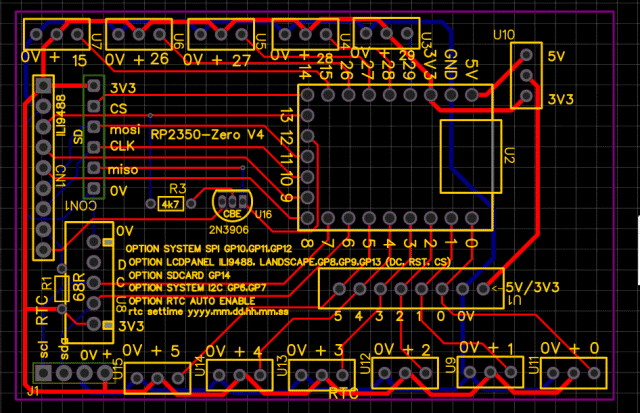  An earlier version of this was the first one I've had where the 680 resistor failed to keep the ILI9488 MISO signal from fouling the SD card. So I used a 2N3906 PNP transistor to gate the MISO signal with *CS. Gerbers are attached. JLCPCB shipping to the U.S. went up from about $3.30 2 weeks ago to $6.60 now. Still, 5 pcbs for under $2 each is quite a bargain compaired to what I paid a dozen years ago. Gerber_RP2350-Zero-breakout_V4.zip PicoMite, Armmite F4, SensorKits, MMBasic Hardware, Games, etc. on FOTS |
||||
| phil99 Guru Joined: 11/02/2018 Location: AustraliaPosts: 3321 |
You were lucky, none of my SD cards worked reliably with the 680Ω. At first I used a PN200 transistor which worked well but when others tried different transistors it didn't work. Eventually I found the transistor can be replaced with a diode. Any type with a junction capacitance greater than about 30pF will work such as 1N4004 or 1N5819. The anode goes to LCD_DO and the cathode to MISO via T_DO. The resistor (1.8kΩ to 10kΩ) goes from LCD_CS to MISO via T_DO. They can be mounted directly on the top of LCD pins. Snipping off the LCD_DO pin then makes it compatible with boards intended for other displays. . Edited 2026-03-30 11:01 by phil99 |
||||
| lizby Guru Joined: 17/05/2016 Location: United StatesPosts: 3811 |
Thanks, Phil. I had seen your post about the diode (also got the transistor idea from you--why might it not work?), but it didn't really register. I don't have touch wired here, so no signal to T_DO. PicoMite, Armmite F4, SensorKits, MMBasic Hardware, Games, etc. on FOTS |
||||
| phil99 Guru Joined: 11/02/2018 Location: AustraliaPosts: 3321 |
Two possibilities are: 1) Capacitance. With the diode I found junction capacitance was important. A 1N4148 only has about 6pF and will only work with 22pF or more in parallel. Perhaps that applies to transistors also. 2) Reverse gain. MISO needs to be driven high and low so sufficient gain is also needed in the reverse direction (collector positive, emitter negative). The PN200 I used has a forward gain of around 500 and I measured about 30 in reverse. You won't find it in a datasheet so you need to do a breadboard test. It only works with a supply voltage below about 6V as that is the B-E reverse breakdown voltage. |
||||
| Volhout Guru Joined: 05/03/2018 Location: NetherlandsPosts: 5994 |
Phil, Lizby, Why not use a single gate 74lvc1G125. .enable to lcd chip select. Alternatieve is a small PFET.. gate to lcd chip select, source to lcd miso. BSS84 or alike. Volhout Edited 2026-03-30 15:18 by Volhout PicomiteVGA PETSCII ROBOTS |
||||
| phil99 Guru Joined: 11/02/2018 Location: AustraliaPosts: 3321 |
I expect a PFET would work if it doesn't have a body diode. If the PFET has a body diode the anode (connected to the drain) would need to be connected to LCD_DO as that pin goes low when idle, The body diode needs to be reverse biased when idle. The PFET would then be a source follower so its gate threshold voltage would need to be lower than the 1 to 0 transition voltage of the Pico. I have found the diode plus resistor method to be very reliable and simple to implement. It is just a matter of using a suitable diode, which can be from a wide range of common types. Edited 2026-03-30 17:30 by phil99 |
||||
| The Back Shed's forum code is written, and hosted, in Australia. | © JAQ Software 2026 |
