Notice. New forum software under development. It's going to miss a few functions and look a bit ugly for a while, but I'm working on it full time now as the old forum was too unstable. Couple days, all good. If you notice any issues, please contact me.
matherp Guru Joined: 11/12/2012 Location: United KingdomPosts: 12051
Posted: 05:22pm 24 Jun 2026
Copy link to clipboard
Print this post
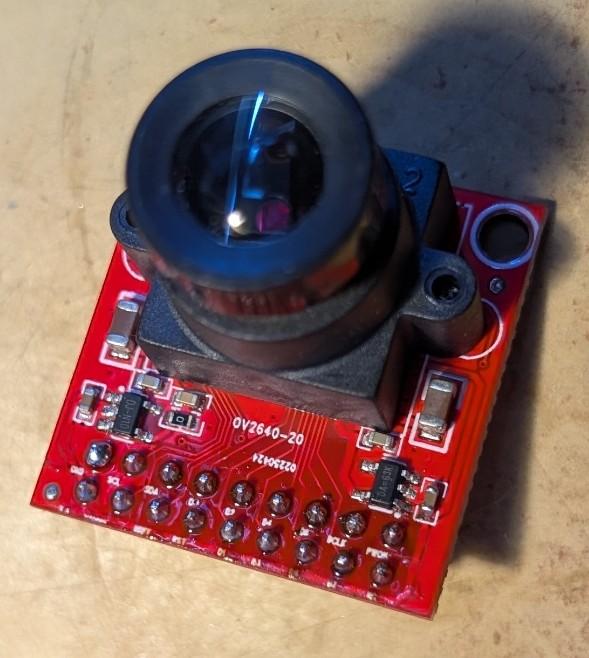
Version 6.03.00RC25 onwards will have support for the OV2640 camera module that is now ubiquitous and a significant update from the OV7670 that has been supported in multiple versions of MMbasic.
The OV2640 support is available on all RP2350 builds except VGA, VGAUSB and HDMIWEB. For the HDMI and HDMI builds you must be in mode 4 (RGB555) to use the camera. For the PicoMite builds you will need a connected SPI display (with working MISO) and have enough memory free for the firmware to allocate a 153600 byte buffer in main ram (not PSRAM). The basic resolution used is 320x240 RGB565 - hence the 153600 byte buffer and the firmware supports capture of images at that resolution and an image change algorithm that will detect motion in the camera field.
All good so far BUT the PicoMite OV2640 firmware also supports jpeg capture in resolutions up to 1600x1200. This allows for a trivial program that can monitor the visual fields for movement and then capture the image in much higher resolution.
Here is the manual entry for the new firmware
There is also a minor enhancement to the LOAD JPG command to allow images to be downscaled to making reviewing easier.
Taken together, these changes allow a simple motion detection program
Option explicit Option default none Dim float ch Dim imag%(320*240\8-1) Dim s$ If Instr(MM.DEVICE$,"HDMI") Then Mode 4 Drive "b:" Camera open ov2640 gp20,gp21,gp22,gp26,gp27,gp0 Do Camera change imag%(),ch' initialise the change image Do Camera change imag%(),ch,1 Loop Until ch>10 s$="Movement" Inc s$, LEFT$(Date$,2)+Mid$(Date$,4,2)+RIGHT$(Date$,2) Inc s$," "+LEFT$(Time$,2)+Mid$(Time$,4,2)+RIGHT$(Time$,2)+".jpg" Camera capture jpeg s$,sxga Load jpg s$,,,,,4 Pause 2000 Loop
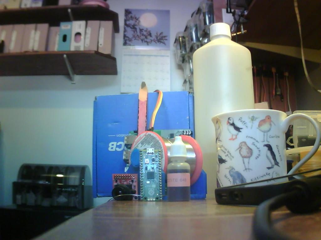
Here is a sample image taken at 1600x1200 using my HDMIUSB reference board to control the camera
PhenixRising Guru Joined: 07/11/2023 Location: United KingdomPosts: 2100
Posted: 10:19pm 24 Jun 2026
Copy link to clipboard
Print this post
Do you know if these cameras are IR sensitive, Pete? I only got a definite maybe from AI.
al18 Senior Member Joined: 06/07/2019 Location: United StatesPosts: 252
Posted: 01:10am 25 Jun 2026
Copy link to clipboard
Print this post
Nice. I see Amazon has the camera on sale for $7.99 during Prime days.
On your picture, it looks like the red color of the camera PCB is being displayed as pink. The blue of the JLCPCB box and the green Raspberry Pico 2 looks correct.
matherp Guru Joined: 11/12/2012 Location: United KingdomPosts: 12051
Posted: 07:05am 25 Jun 2026
Copy link to clipboard
Print this post
I think they may have an IR filter but if so it is a crap one (tested with a TV remote). I couldn't get good pictures looking outside but, of course, the weather here is very hot, bright and hazy so not a good test.
Agreed, there are a gazillion registers you can change on these things to tune the colour but this could also be affected by the IR issue. I'm waiting on some IR filters to see if that improves things.
Bryan1 Guru Joined: 22/02/2006 Location: AustraliaPosts: 2297
Posted: 07:24am 25 Jun 2026
Copy link to clipboard
Print this post
So Peter does this new camera work with a 2350-2W webmite and if so now I got the wifi fixed around the farm it would be nice to get that project done so expect plenty off kangaroo pictures to come up.
Regards Bryan
matherp Guru Joined: 11/12/2012 Location: United KingdomPosts: 12051
Posted: 07:54am 25 Jun 2026
Copy link to clipboard
Print this post
The camera can be used on the 2350-2W webmite assuming you have enough pins free. Must be fun having kangaroos to see, all I get is the neighbours cats crapping in the vegetable bed Edited 2026-06-25 17:55 by matherp
TassyJim Guru Joined: 07/08/2011 Location: AustraliaPosts: 6626
Posted: 08:26am 25 Jun 2026
Copy link to clipboard
Print this post
Chasing them out of the vege garden every morning is good exercise.
Even more exciting is getting a Tassy Devil out of the bathroom.VK7JH MMedit
matherp Guru Joined: 11/12/2012 Location: United KingdomPosts: 12051
Posted: 08:27am 25 Jun 2026
Copy link to clipboard
Print this post
Different world
v.lenzer Senior Member Joined: 04/05/2024 Location: GermanyPosts: 157
Posted: 09:55am 05 Aug 2026
Copy link to clipboard
Print this post
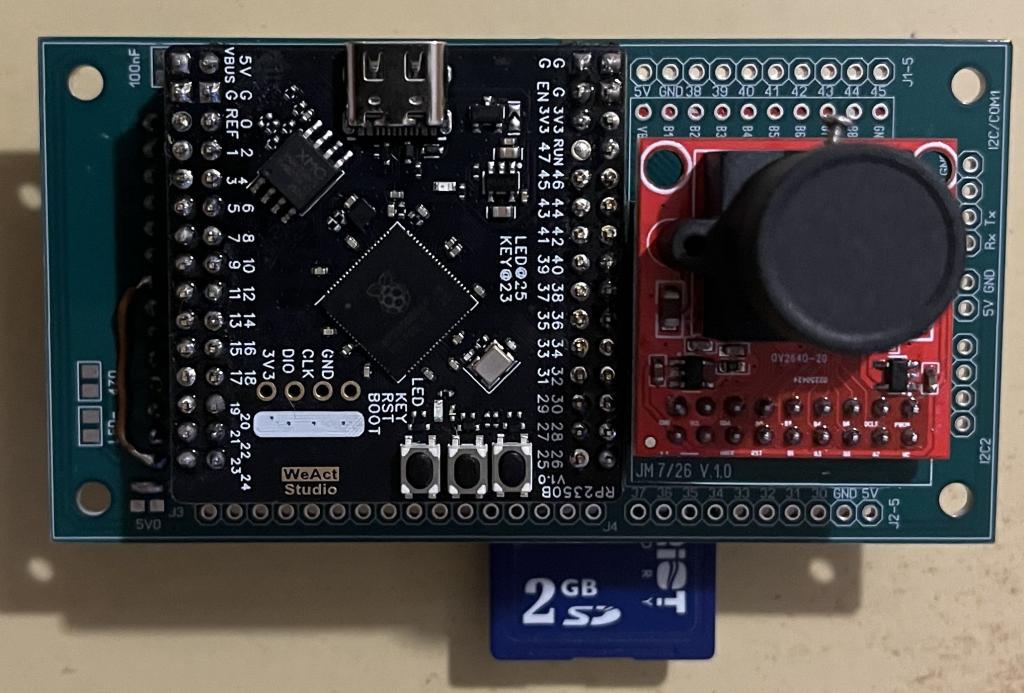
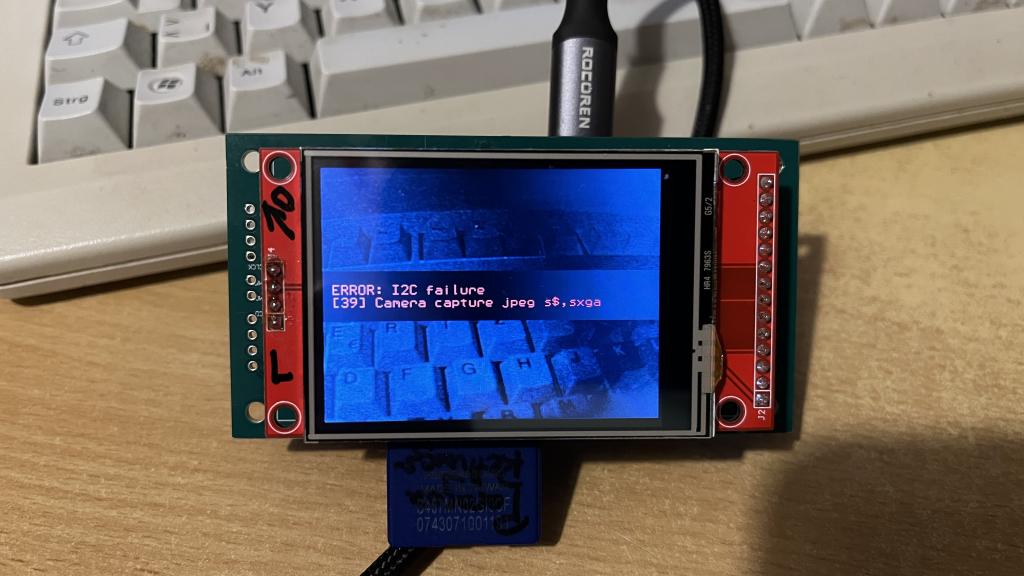
Hi Peter! I’ve connected an OV2640 camera to the WeAct board featuring the RP2350B (along with 6MB of PSRAM). I get an image using the commands: "Camera open ov2640 gp40,gp41,gp42,gp43,gp44,gp30" and "Camera capture". So, everything is fine up to that point. Unfortunately, I cannot use the "Camera capture jpeg" command. Your "Motion Detector" program crashes with the message: "Camera capture jpeg s$,sxga Error: I2C failure". Only "Camera" is listed under "List Commands". Is "Camera capture jpeg" not included in the firmware I flashed onto the RP2350B? Here are my options:
And one more question on the subject: I keep seeing an image that is upside down, no matter how I rotate the camera. Is this due to the camera settings?
I would really appreciate any help from you or the others!Best wishes! Joachim
matherp Guru Joined: 11/12/2012 Location: United KingdomPosts: 12051
Posted: 10:40am 05 Aug 2026
Copy link to clipboard
Print this post
transitioning between modes capture to jpeg for example chucks hundreds of commands at the i2c port. Based on your description i would be suspicious of the i2c wiring. Do you have enough pullup but not too much. How long are the cables to the camera? As to the image upside down, that makes no sense, the image has to be relative to the camera orientation. If the camera is on an angle the image is on an angle. There are register commands than can flip the image and mirror it but they can't compensate for angles and AFAIK the camera doesn't auto-compensate
v.lenzer Senior Member Joined: 04/05/2024 Location: GermanyPosts: 157
Posted: 02:07pm 05 Aug 2026
Copy link to clipboard
Print this post
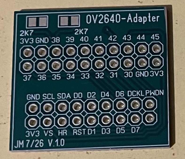
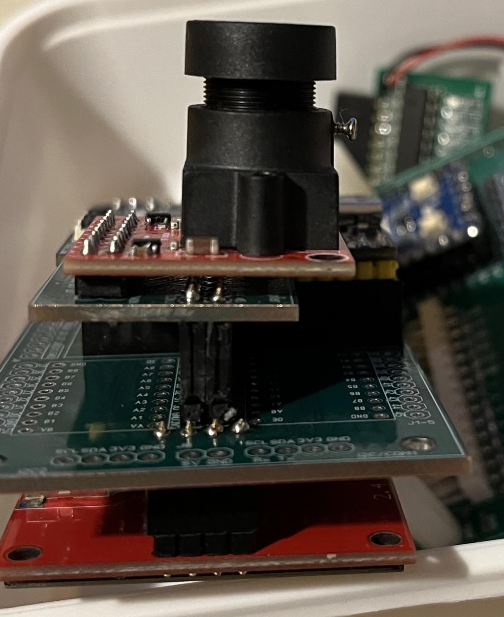
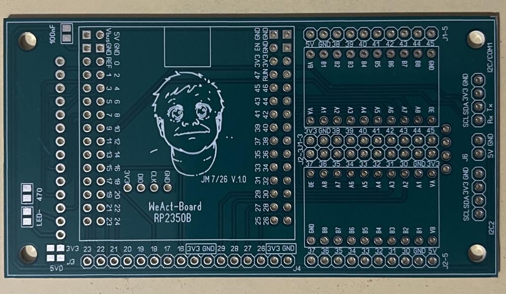
Hi Peter! Thanks a lot for your quick reply! I designed an adapter board to which I solder the camera module, allowing me to plug it directly into the port connectors. This keeps the cable length to a maximum of 2 cm. However, I didn't have any 2.7k SMD resistors on hand and hoped that 4.7k ones would work too. That is obviously the reason. Okay, I'll try using standard resistors until I can get hold of some 2.7k SMD ones. I'll get back to you with photos regarding the image orientation. Here are a few photos of my WeAct board and the adapter board.
Best wishes! Joachim
v.lenzer Senior Member Joined: 04/05/2024 Location: GermanyPosts: 157
Posted: 02:49pm 05 Aug 2026
Copy link to clipboard
Print this post
For a quick-and-dirty solution, I soldered two 4.7k resistors in parallel. The pull-up value is now 2.3k ohms. Unfortunately, the same error message appears.
Here the program:
Motion-detector 'by Peter Mather, the back shed-forum
Dim float ch Dim imag%(320*240\8-1) Dim s$ If Instr(MM.DEVICE$,"HDMI") Then Mode 4 Drive "b:" Camera open ov2640 gp40,gp41,gp42,gp43,gp44,gp30
do while inkey$="" camera capture loop
Do Camera change imag%(),ch' initialise the change image Do Camera change imag%(),ch,1 Loop Until ch>10 s$="Movement" Inc s$, LEFT$(Date$,2)+Mid$(Date$,4,2)+RIGHT$(Date$,2) Inc s$," "+LEFT$(Time$,2)+Mid$(Time$,4,2)+RIGHT$(Time$,2)+".jpg" Camera capture jpeg s$,sxga Load jpg s$,,,,,4 Pause 2000 Loop
do while inkey$="" camera capture loop
This is just there to view and check the image in color.
do while inkey$="" camera capture loop
This is just there to view and check the image in color.
A JPG file named "Movement ...." is created. However, the file is 0 bytes in size.
Or could it be that I configured the I2C interface incorrectly? I entered `OPTION SYSTEM I2C GP38,GP39`. However, GP38/39 correspond to I2C2. Or does that not matter? Edited 2026-08-06 01:00 by v.lenzerBest wishes! Joachim
v.lenzer Senior Member Joined: 04/05/2024 Location: GermanyPosts: 157
Posted: 09:28pm 06 Aug 2026
Copy link to clipboard
Print this post
Hi Peter! The motion detector is working now with these changes. It’s not JPEG quality—just BMP—but it serves its purpose.
Do Camera change imag%(),ch' initialise the change image Do Camera change imag%(),ch,1 Loop Until ch>10 s$="Movement" Inc s$, LEFT$(Date$,2)+Mid$(Date$,4,2)+RIGHT$(Date$,2) Inc s$," "+LEFT$(Time$,2)+Mid$(Time$,4,2)+RIGHT$(Time$,2)+".bmp" Camera capture save image s$ Load bmp s$ Pause 2000 Loop

 Notice. New forum software under development. It's going to miss a few functions and look a bit ugly for a while, but I'm working on it full time now as the old forum was too unstable. Couple days, all good. If you notice any issues, please contact me.

 Print this post