Volhout

Guru

Joined: 05/03/2018
Location: NetherlandsPosts: 6195 |
| Posted: 07:13am 25 Aug 2026 |
 Copy link to clipboard Copy link to clipboard |
 Print this post |
|
For a WWII interactive display I was asked to create a mockup of a listening station, as used for intercepting Enigma messages.
One of the radio receivers used for this work was the RCA AR88, a receiver that even today is a collectors item (read: expensive when working). Also for it's formidable performance.
I found high resolution photo's on the web that where laser printed, and glued on wood, and found on ebay scans of the dials (to support the purchase of the real thing). The dials where printed on glossy paper, and sleeved. The frequency dial was glued on a RC servo, the fine tune dial was attached to a geared stepper motor driven from ULN2003. The main tuning knob was designed in OpenSCAD from photo's, and 3D printed. The knob drives a optical quadrature encoder (found on a flea market, but appeared to be an expensive part).
A demo of the prototype stage is visible here (note, you can download the MP4, but it is 55Mbyte, better you play it on Google Drive).
AR88 demo
The video is taken in proto stage, to show the team at the exhibition what was comming. Cosmetics have been improved since, as well as the software. But the behaviour is very AR88 (you can give the large knob a good swing, and it will continue to rotate 2 seconds, rotating the frequency dial all the way, but also milimeter movements will show nicely).
Internals
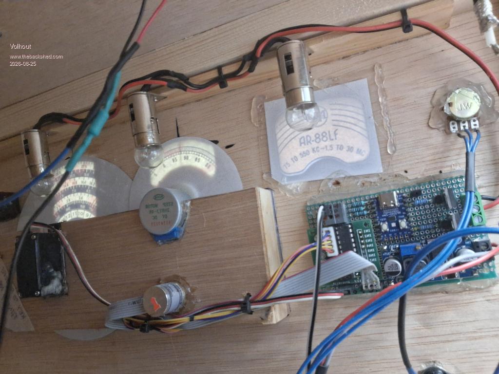
The output is a RS232 output just sending the rotary encoder numbers, to a backend running on a PC that plays audio streams from a python script (morse codes, and sound samples from the era) accompanied by WWII photo's..
The program that controls the servo, and stepper, from quadrature input is all MMBasic running on a Pico Zero (RP2040). The PIO is used to decode quadrature.
'create a AR88 WW2 receiver with coarse and fine dial, driven from a
'quadrature encoder
'the quadrature decoder runs on PIO
'the fine dial is driven by a stepper motor (must rotate multi turns)
'the coarse dial is driven from a servo (180 degrees max)
'send strings to main RP (text t.b.d)
'hardware : 64*64 stepper = 4096 per revolution
'hardware : 125*4 quadrature encoder = 500 per revolution
'softwaare gain needed = 4096/500 = 8
'stepper driver
Option default integer
'system initialisation -------------------------------------------------------
'inti the stepper control pins
initio
' variables for stepper
Dim phases(7)=(&b0001,&b0011,&b0010,&b0110,&b0100,&b1100,&b1000,&b1001)
Dim steps2go=0, quadra,quadra_old, delta, limh
'stepper motor can make 1000 steps per second max. In a 20ms loop equals
limh = 1000 * 0.02
'set the max speed of the stepper at 1ms per step (1kHz)
SetTick 1,step_it
'variable for servo
dim positio!,rot=1
'program PIO 1
program_PIO 'program the code in PIO 1
'start quadrature decoders (uncomment the needed decoders)
start_sm0 'start decoder on GP7 and GP8
zero_sm0 'zero quadrature
'main program loop --------------------------------------------------------
Do
'INPUT read PIO FIFO for quadrature changes
quadra = -read_fifo(0)
'debug
'print str$(quadra,12,0) 'get data from decoder
'OUTPUT to stepper
'add delta fifo since last read to stes2go (pos or neg)
delta=quadra_old-quadra:quadra_old=quadra
'limit the pulse speed to the max the stepper can handle to avoid lag
delta = max(min(delta*8,limh),-limh) '8 = software gain
'output the value
if rot then Inc steps2go,delta else steps2go=0
'OUTPUT to SERVO : add delta fifo to servo pos
'PWM 3,50,(position_as_a_percentage * 0.05 + 5)
positio! = 7.5 + 0.0025 * quadra : rot=1
if positio!<3 then positio!=3 : rot=0 'hardware limit
if positio!>11.5 then positio!=11.5 :rot=0 'hardware limit
PWM 3,50,positio!
'OUTPUT send delta to UART
print #1,str$(quadra,6,0) 'get data from decoder
Pause 20 'loop speed
Loop While Inkey$=""
PIO stop 1,0
PIO clear 1
End
' subroutines ---------------------------------------------------------------
'zero counter state machine 0
Sub zero_sm0
PIO execute 1,0,&hA023 '= assembly "mov X, null" (zero X reg)
End Sub
'this function returns the actual count of decoder n
Function read_fifo(n) As integer
Local dat%(3)
PIO read 1,n,4,dat%() 'read whole fifo
read_fifo = dat%(3) 'last data in fifo
If read_fifo>2147483647 Then Inc read_fifo,-4294967296 '2'th complement
End Function
'this subroutine programs the quadrature decoder program for PIO1 into PIO program memory
Sub program_PIO
'this is the PIO program in machine code
dim p%(7)=(&h001A00170015001A,&h0015001A001A0017,&h0017001A001A0015, &h001A00150017001A,&h4042A0404042A0C3,&hA029001A005AA0A6,&h8000A0C1A0290059,0)
'here the program is programmed in memory
PIO program 1,p%()
wrap=27 'end of the program
wrp_tgt=16 'start of the program loop
End Sub
'this subroutine starts state machine 0 quadrature decoder on gp12 and gp13
Sub start_sm0
'uses GP12,GP13, assign pins in MMBasic
SetPin gp7,pio1
SetPin gp8,pio1
'quadrature decoders generic settings
PIO_f%=63e6 'frequency = 63MHz
PIO_s%=0 'shift register (shift in left)
PIO_e%=Pio(execctrl gp0,wrp_tgt,wrap) 'start and stop of the loop
'assign pins in PIO
pin_sm0%=Pio(pinctrl 0,0,0,gp7)
'configure and start PIO
PIO init machine 1,0,PIO_f%,pin_sm0%,PIO_e%,PIO_s%,wrp_tgt
PIO start 1,0
End Sub
'inits stepper output signals on GP2...5
Sub initio
local brightness=75 'default 75% (3/4 of 4S lipo)
'init stepper pins to dout and low
For i=2 To 5
SetPin "GP"+Str$(i),dout :Pin("gP"+Str$(i))=0
Next
'use PWM3A f=to drive a servo
setpin gp6,PWM
PWM 3,50,7.5 'mid position
'use PWM7A/B to dim light bulbs
setpin gp14,pwm
setpin gp15,pwm
pwm 7,1000,100-brightness,100-brightness 'inverted output = 100%-brightness
setpin gp1,gp0,com1
open "COM1:115200" as #1
End Sub
'moves the stepper until step2go is zero
Sub step_it
Static ps=0
Local dn
If steps2go<>0 Then
Inc steps2go,Choice(steps2go<0,1,-1)
dn=Choice(steps2go<0,7,1)
Inc ps,dn:ps=ps Mod 8
Port(GP2,4)=phases(ps)
End If
End Sub
Volhout
P.S. 0% AI used
.
Edited 2026-08-25 18:31 by Volhout
PicomiteVGA PETSCII ROBOTS |

 Notice. New forum software under development. It's going to miss a few functions and look a bit ugly for a while, but I'm working on it full time now as the old forum was too unstable. Couple days, all good. If you notice any issues, please contact me.