Notice. New forum software under development. It's going to miss a few functions and look a bit ugly for a while, but I'm working on it full time now as the old forum was too unstable. Couple days, all good. If you notice any issues, please contact me.
matherp Guru Joined: 11/12/2012 Location: United KingdomPosts: 12152
Posted: 07:19pm 07 Nov 2026
Copy link to clipboard
Print this post
VT2350: a stand-alone VT100 terminal on an RP2350 The Colour Maximite 2 now has a VT100 terminal application, and VT2350 is the same idea on its own board. It runs on an RP2350 with no PSRAM. Give it an HDMI monitor, a USB keyboard and a serial line, and it is a terminal for a PicoMite, a Linux machine or anything else with a serial console. No PC is needed.
It uses the PicoMite's code for HDMI and the USB keyboard and mouse, and the CMM2 application's terminal, which is built on libvterm.
What it does • 640 x 480 in 256 colours on HDMI, with seven font sizes from 128 x 60 characters down to 40 x 15. • Two UARTs on GP0/GP1 and GP4/GP5, at up to 921600 baud, or up to four USB serial devices through a hub. • A USB keyboard in six layouts, and a USB mouse. • VT100 and VT52, xterm's 256 colours, UTF-8, CP437 and Latin-1, double-width and double-height lines, and scrollback. • A setup menu on Shift-F12, with the settings saved in flash. • All twelve function keys and Ctrl-C go to the host, and the keys are sent the way a PicoMite expects them. When a PicoMite asks for a screen size, at EDIT, FM or OPTION DISPLAY, the terminal changes font to fit.
The smallest build Apart from a monitor and a keyboard, this is all you need:
• A Pico 2 • An HSTX DVI sock • A micro-USB to USB-A socket adapter • An unpowered USB hub • A 5 V supply rated at 2 A, connected to VBUS (pin 40) and GND (pin 38)
There is nothing else to wire, and the sock needs no straps. It has to be VBUS, as power on VSYS doesn't reach the USB socket. Never connect the 5 V supply and a PC at the same time: take the supply off before you plug the Pico 2 into a PC to load the firmware.
Different HDMI wiring Boards wire the HDMI pairs in different orders, so one firmware handles them all. Tie GP6 and GP7 to ground or 3.3 V, or leave them open, to choose from a list that includes the HSTX sock, the Pico Computer 3 and the Olimex boards.
Any other wiring can be set from the menu, using the same four numbers as OPTION HDMI PINS. If you have no picture at all, press Shift-F12 and then W to step through the list without being able to see the screen. A new wiring goes back by itself after 10 seconds unless you keep it.
How fast it is At 80 columns it keeps up with a continuous stream of short lines at 921600 baud. In the two smallest fonts that is too fast for it, but with XON/XOFF turned on nothing is lost. A PicoMite on USB serial sent 1.7 MB at 81 KB/s with every byte received.
Try it Download VT2350.uf2 from here: https://github.com/UKTailwind/VT2350/releases
I've only run it on a Pico Computer 3 so far, so I'd be glad to hear how it goes on a Pico 2 with an HSTX sock.
mozzie Guru Joined: 15/06/2020 Location: AustraliaPosts: 503
Posted: 03:35pm 08 Nov 2026
Copy link to clipboard
Print this post
G'day Peter, What can I say but thanks again for making this possible
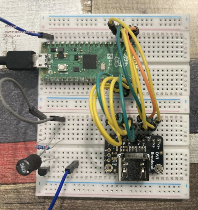
Tested on the trusty HDMI-BreadBoard adaptor and works with both HDMI PINS 1,3,5,7 and 2,0,6,4 (after re-wiring)
Wireless combo keyboard/mouse working ok PicoMites working ok CP2102 USB-TTL working ok FT232 USB-TTL working ok
So far no joy with: MM2 Serial Port - No response MM+ Serial Port - No response MicroBridge - No response
It would appear my old terminal test unit was still running V6.02.02b2, this was the only version to support the MicroBridge / MM2 / MM+ serial CDC. It looks like it was never included in the main build. From V6.02.02b4 onward they don't seem to work, would it be possible to rectify the situation and add support here and in the latest V7 build?
The only other wish list item would be the Heartbeat LED, hard to know if its alive or not if the screen is dead and no heartbeat flashing.
My thanks once again. (and also to Claude)
Regards, Lyle.
dddns Guru Joined: 20/09/2024 Location: GermanyPosts: 925
Posted: 03:52pm 08 Nov 2026
Copy link to clipboard
Print this post
Thank you for this! I will try it asap.
It would be great if you could add LCD panel support.
I was always looking for a Basic implementation. Would it be possible to have a lite version of this for MMBasic?
matherp Guru Joined: 11/12/2012 Location: United KingdomPosts: 12152
Posted: 04:00pm 08 Nov 2026
Copy link to clipboard
Print this post
For the MM2, just use a direct connection of gp0/Gp1 to the relevant mm2 pins. I can't see why this wouldn't work. It has been tested on loopback on both com0 and com1
mozzie Guru Joined: 15/06/2020 Location: AustraliaPosts: 503
Posted: 04:50pm 08 Nov 2026
Copy link to clipboard
Print this post
G'day Peter, Apologies, should have written: MM+ USB CDC - No response MM2 via MicroBridge - No response
Most of the boards here are based on the Silicon Chip MicroMite LCD Backpack PCB and have the MicroBridge fitted, the kit from SC comes with both chips.
I feel it would be a shame for such a great terminal program to not support the MMite / MicroBridge, these are still an awesome combination for simpler projects. It was a bummer to realize they appear to be not supported by the PicoMite CDC serial, I had tested them back in V6.02.02b2 and they worked well.
I will test the direct serial connection by removing the MicroBridge from a board.
Thanks again.
Regards, Lyle.
matherp Guru Joined: 11/12/2012 Location: United KingdomPosts: 12152
Posted: 06:26pm 08 Nov 2026
Copy link to clipboard
Print this post
If you download again you should find the Microbridge now works
bfwolf Senior Member Joined: 03/01/2025 Location: GermanyPosts: 265
Posted: 08:17pm 08 Nov 2026
Copy link to clipboard
Print this post
Do you think it would be possible and worth the effort, to make it also available in PicoMite as a CSUB?
This would allow using a PicoMite RP2350 as a terminal "on demand"..
Perhaps it would even be possible to be used by MikeV73's PicoMite with integrated C-compiler?
Kind regards.
mozzie Guru Joined: 15/06/2020 Location: AustraliaPosts: 503
Posted: 01:26pm 09 Nov 2026
Copy link to clipboard
Print this post
G'day Peter, Indeed it does, so far everything plugged in works:
PicoMite - working OK CH340 - working OK CP2102 - working OK FT232 - working OK MicroBridge - working OK MM+ USC CDC - working OK
The only glitch noticed is if OPTION COLOURCODE ON is set in MM2/MM+ the status line text is not shown. Possibly wrong colour?
Will test TTL serial connection tomorrow with a little luck.

 Notice. New forum software under development. It's going to miss a few functions and look a bit ugly for a while, but I'm working on it full time now as the old forum was too unstable. Couple days, all good. If you notice any issues, please contact me.


 Print this post