Notice. New forum software under development. It's going to miss a few functions and look a bit ugly for a while, but I'm working on it full time now as the old forum was too unstable. Couple days, all good. If you notice any issues, please contact me.
matherp Guru Joined: 11/12/2012 Location: United KingdomPosts: 12220
Posted: 03:08pm 15 Nov 2026
Copy link to clipboard
Print this post
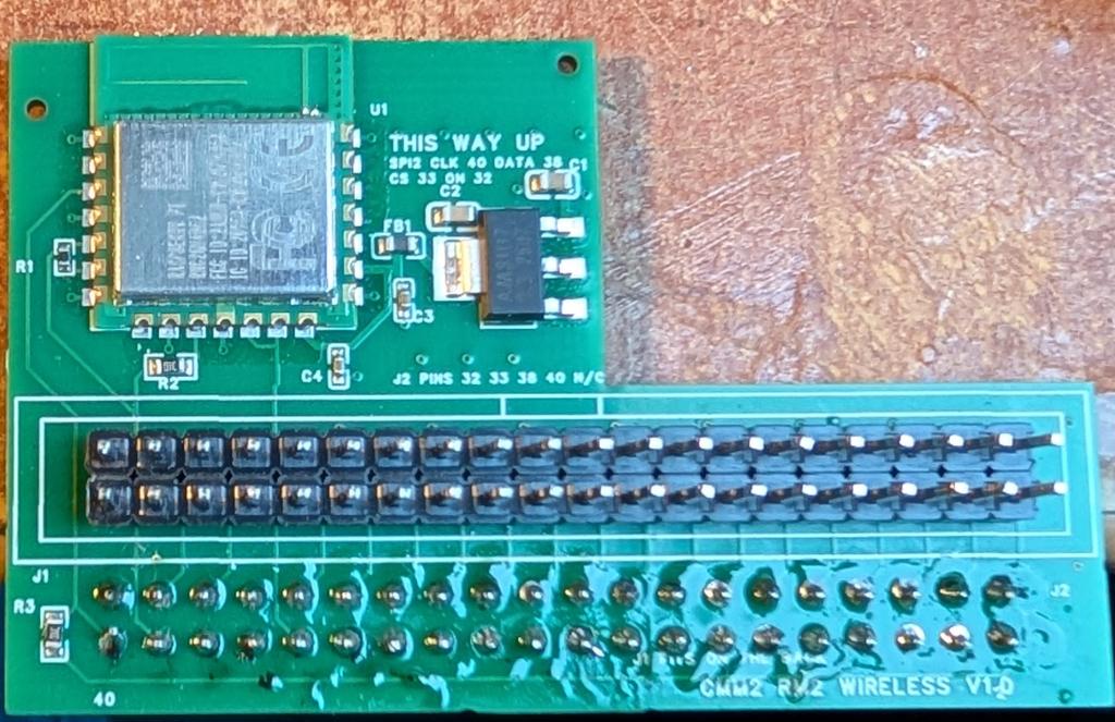
See https://mather.host/cmm2/wifi/ for full details, links to gerbers etc. The final board is designed so it is possible to hand solder, nothing smaller than 1206, or you can get it made up by JLC. Don't get them to solder the headers, it will add significant extra cost. Software support will be in the first V8.00.00 beta which will be posted in the next couple of days. It has been tested with Geoff's watering controller software and works perfectly
Mixtel90 Guru Joined: 05/10/2019 Location: United KingdomPosts: 9364
Posted: 03:13pm 15 Nov 2026
Copy link to clipboard
Print this post
Excellent news! I'm hoping that you'll be considering Bluetooth then I can get rid of some wires... ;)Mick
matherp Guru Joined: 11/12/2012 Location: United KingdomPosts: 12220
Posted: 03:16pm 15 Nov 2026
Copy link to clipboard
Print this post
Give us a chance
Mixtel90 Guru Joined: 05/10/2019 Location: United KingdomPosts: 9364
Posted: 03:27pm 15 Nov 2026
Copy link to clipboard
Print this post
No prob. :) On a G1, it looks like you need to stand the CMM2 on something. It looks relatively high to me. Would the answer be to use a 90 degree plug on that, and poke the board out horizontally?Mick
matherp Guru Joined: 11/12/2012 Location: United KingdomPosts: 12220
Posted: 04:02pm 15 Nov 2026
Copy link to clipboard
Print this post
sound good, you just need to make sure in you use a keyed plug that it is the correct way round for the specific board G1 or G2/G3
PhenixRising Guru Joined: 07/11/2023 Location: United KingdomPosts: 2154
Posted: 04:45pm 15 Nov 2026
Copy link to clipboard
Print this post
Quite right; expecting any more than 25,000 tasks at any time is pushing it a bit, I'd say
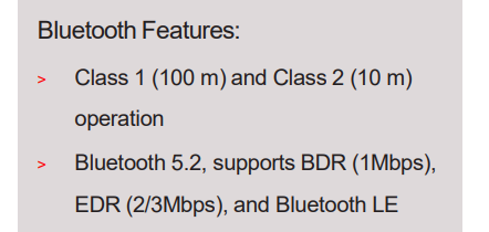
Class-1 BT? Holy moly. Is this something we have along with Class-2 or just ignored? I have only dealt with industrial Class-1 devices and in my case, the 100m range is conservative.
External antenna possible?
Mixtel90 Guru Joined: 05/10/2019 Location: United KingdomPosts: 9364
Posted: 04:55pm 15 Nov 2026
Copy link to clipboard
Print this post
AFAIK the bump polarized 90 degree plugs are always "bump away from board", you don't have a choice.
I'm just looking at a G1. Looking down on the board from the front of it (not from the rear panel) pin 40 is bottom left (same as the wifi board) with bump to the top.
If using a 90 degree keyed header on top of the wifi board it can't work as it then puts 39 where 40 is marked on the wifi board. (fitting it to the bottom reverses the connector).
if using an un-keyed header mounted on the bottom of the wifi board then it works.
matherp Guru Joined: 11/12/2012 Location: United KingdomPosts: 12220
Posted: 05:01pm 15 Nov 2026
Copy link to clipboard
Print this post
You want an unkeyed right angle female header mounted to the bottom of the board for a G1. The way the pins will stick up and the wifi module will be on the top. For the G2 stick with the straight header. Of course the other approach is a male female 40pin IDC cable
Mixtel90 Guru Joined: 05/10/2019 Location: United KingdomPosts: 9364

 Notice. New forum software under development. It's going to miss a few functions and look a bit ugly for a while, but I'm working on it full time now as the old forum was too unstable. Couple days, all good. If you notice any issues, please contact me.


 Print this post


 Holy moly. Is this something we have along with Class-2 or just ignored?