
|
|
Forum Index : Microcontroller and PC projects : PWM - not sure...
| Page 1 of 2 |
|||||
| Author | Message | ||||
| Mixtel90 Guru Joined: 05/10/2019 Location: United KingdomPosts: 8965 |
How long does it take for the PWM mark/space value to update? I'm asking because I had an idea for a very crude Pico controlled power supply yesterday but I'd need to get my scope out of its temporary storage to test the idea. I'm considering using a PWM output to pulse a mosfet which feeds a reservoir capacitor across the output. A sample of the output voltage is fed back into an ADC input to form a control loop which adjusts the mark/space ratio. I know that the cap will compromise the loop speed but I'm not terribly bothered. If the PWM frequency is around 20kHz it won't need to be all that big. A high side current monitor chip before the mosfet can give another input for current regulation. That will have pulses on it, but those can be smoothed out a bit. Just an idea at this stage. Mick Zilog Inside! nascom.info for Nascom & Gemini Preliminary MMBasic docs & my PCB designs |
||||
| matherp Guru Joined: 11/12/2012 Location: United KingdomPosts: 11647 |
The update is at the end of the PWM loop so at 20KHz it can update once every 1/20000 seconds + any MMBasic processing time Edited 2025-03-31 19:58 by matherp |
||||
| Volhout Guru Joined: 05/03/2018 Location: NetherlandsPosts: 5994 |
@Mick, I went through this for my PWM controlled linear power supply. To get 16 bit resolution in a pico (peripheral clock = 63 or 66MHz) the PWM frequency must be 1kHz or lower. To achieve less that 1mV ripple, the filter attenuation must be 70dB or more. Following filter can be used, giving 72dB attenuation at 1kHz. 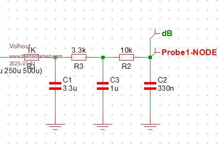 This filter has 16ms delay and settles within 1% in 40ms. Maybe this si fast enough. 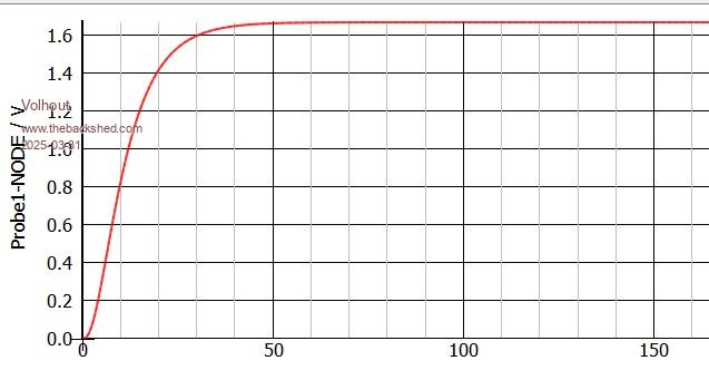 I am not sure if this is acceptable for your application. If you need less resolution, your PWM frequency can be higher, and delays get less. If you can accept more ripple, you can make a simpler filter, and delays can be less. Some can be optimized using active filters. EDIT: are re-reading the first post: you are building a MMBasic controlled switchmode power supply. So this is not relevant. Building a MMBasic controlled switchmode PSU: yes, can be done. I did it before building a high voltage generator (flyback) with feedback. Very simple, only proportional feedback (no PID). But with PID would have been better. Tip up front: calculate the max PWM, and limit the control loop to that PWM. I didn't and burned several power FET's before I got the control loop right. Volhout Edited 2025-03-31 20:31 by Volhout PicomiteVGA PETSCII ROBOTS |
||||
| Mixtel90 Guru Joined: 05/10/2019 Location: United KingdomPosts: 8965 |
For a maximum output of around 18V (a typical laptop power brick is 19V) I think 12 bit resolution will do fine. 10 bit would probably be ok. This isn't intended to be a lab quality supply, just a hobby project. Cost is very important. There's no point in trying to compete with ready made Chinese modules. If it works out much more than one of those then you are better getting one. Mick Zilog Inside! nascom.info for Nascom & Gemini Preliminary MMBasic docs & my PCB designs |
||||
| PhenixRising Guru Joined: 07/11/2023 Location: United KingdomPosts: 2006 |
Wait, what? This has been an issue for me: pwm 1,18000,mcmd I'm hoping that I've done something dumb here because I have tested many times and this line adds >1mS to my code execution. I have, therefore, dropped PWM and gone with a SPI DAC. |
||||
| matherp Guru Joined: 11/12/2012 Location: United KingdomPosts: 11647 |
 First time sets up the frequency so takes a bit longer |
||||
| PhenixRising Guru Joined: 07/11/2023 Location: United KingdomPosts: 2006 |
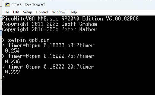
Sure enough, from the command line, I get 0.130 WTF! When I ran it in my code, I confirmed with both TIMER and my scope that REM-ing-out that line, cut my execution by a touch > 1mS. Need to revisit this.  |
||||
| Volhout Guru Joined: 05/03/2018 Location: NetherlandsPosts: 5994 |
For Mick this speed is not so important. Volhout PicomiteVGA PETSCII ROBOTS |
||||
| Mixtel90 Guru Joined: 05/10/2019 Location: United KingdomPosts: 8965 |
I can drop to 10 bits. I think that will just about give me 20kHz for the PWM frequency. I can tweak things around there, I'd just like to avoid too much whistling. I'll probably need overclocking to keep the program scan time down, but I'm going to be at the mercy of the speed of the ADC as well. At the moment I'm envisioning a pretty crude feedback system to link the ADV input to the PWM mark space value. There'll obviously have to be a comparison with a reference value. Filtering the ADC input would slow the system down a bit but at the same time it would also automatically remove some oscillation within the control loop so it's probably a good thing to do. I've not thought much about how things are controlled. To keep cost down probably a little I2C or SPI display and buttons. Possibly a 12-key or even a 16-key scanned keypad? They are cheap, not bad looking and easy to use. It would be cheaper than going for a larger touch screen display and I rather fancy the idea of entering a voltage or current from a keypad. :) Mick Zilog Inside! nascom.info for Nascom & Gemini Preliminary MMBasic docs & my PCB designs |
||||
| Volhout Guru Joined: 05/03/2018 Location: NetherlandsPosts: 5994 |
Mick, I am not sure I understand. Are you planning cycle for cycle control? MMbasic won't do that at any non-audible frequency. You need C-code or assembly to do that (or hardware). I assume you have the PWM run autonomously at 40-200kHz (relates to inductor value) and once per XX ms you look at the output voltage, and tune the PWM value (that is what I did). And since PWM also supports 0, you automatically have pulse skipping at low loads. Since you control the PWM from software, it is not needed to have 10 bits. Worst that can happen is that you have some low frequency ripple due to the low PWM resolution (i.e. toggling between 35% and 34.8% every XX ms). Volhout Edited 2025-04-01 17:07 by Volhout PicomiteVGA PETSCII ROBOTS |
||||
| phil99 Guru Joined: 11/02/2018 Location: AustraliaPosts: 3323 |
Had a play with a possible alternative to PWM. A 1 bit DAC controlled by ADC feedback. Hardware:- Pico 2350 VGA @ 360MHz Switch-mode output stage simulated with a 1.5kΩ from a DOUT pin to a AIN pin and 1µF from AIN to ⏚. do :if pin(gp27)<2 then :pin(gp6)=1:else :pin(gp6)=0:endif :loop Target voltage = 2.0V, output, 1.986V frequency, 7.65kHz ripple, 16.3mV Verdict:- loop time too long, ripple too high. Changed C to 10µF. Target voltage = 2.0V, output, 1.991V frequency, 12.45kHz ripple, 2.4mV Verdict:- much better, the increase in frequency was an unexpected bonus. Edit. C = 10µF. Target voltage = 1.0V, output, 1.001V frequency, 8.921kHz ripple, 2.4mV Edited 2025-04-01 17:10 by phil99 |
||||
| PhenixRising Guru Joined: 07/11/2023 Location: United KingdomPosts: 2006 |
Even at ~12KHz, I hear nothing. If you have a spare Android device and a Bluetooth module for the Pico, I can rustle-up a program for you because I have lots of boiler-plate routines for Bluetooth on Android. The cool thing is that I send [your_prog].apk which will install and run but then you can do a standard unzip of the apk file which reveals the entire interpreter, code and resources (such as bmp files, etc.). |
||||
| matherp Guru Joined: 11/12/2012 Location: United KingdomPosts: 11647 |
Try using SETPIN GP27,ARAW - returns a value 0-4095 but is faster then do :if pin(gp27)<2482 then :pin(gp6)=1:else :pin(gp6)=0:endif :loop you could also try do:pin(gp6)=choice(pin(gp27)<2482,1,0):loop |
||||
| phil99 Guru Joined: 11/02/2018 Location: AustraliaPosts: 3323 |
Thanks Peter, that is better. > SETPIN GP27,ARAW : SetPin gp6,dout > do:pin(gp6)=choice(pin(gp27)<2482,1,0):loop C = 10µF, R = 1.5kΩ Target voltage = 2.0V, output, 1.993V frequency, 15.18kHz ripple, 2.4mV Edit. C = 10µF, R = 1.5kΩ. Target voltage = 1.0V, output, 1.002V frequency, 12.15kHz ripple, 2.4mV Edited 2025-04-01 17:33 by phil99 |
||||
| Mixtel90 Guru Joined: 05/10/2019 Location: United KingdomPosts: 8965 |
I can see that I'm going to have to think further about this. :) No point in over-complicating it. You can get a cheap 3A buck-boost converter, two multiturn pots with knobs, terminals, a switch, a combined voltmeter/ammeter and a 19V laptop PSU for very little now (around £11 on AE). TBH I much prefer a proper transformer/rectifier/capacitor, but they've gone expensive now. You can buy a ready-built switching PSU, cased and ready to use, for less than £35 - even cheaper than buying modules to build a supply. You'll pay more than that for a 150VA transformer. I'm unsure about the fancy panel mounted modules now. I've had one that I screwed up by being silly with the settings and there's no way to do a hard reset. Another has a couple of failing display segments. The more expensive ones *might* be better. :) Mick Zilog Inside! nascom.info for Nascom & Gemini Preliminary MMBasic docs & my PCB designs |
||||
| Volhout Guru Joined: 05/03/2018 Location: NetherlandsPosts: 5994 |
@Phil, It is quite interesting to see that that works, and how fast it is. But it consumes 100% of the MMBasic environment. So the PM is now a quite expensive comparator (1/4 of a LM339 costing $0.08) The idea of using PWM (hardware in pico) and a slower loop is that the pico can run this as a side task (settick controlled). Not as it's main task. I guess that is what Mick is looking for. Volhout PicomiteVGA PETSCII ROBOTS |
||||
| Mixtel90 Guru Joined: 05/10/2019 Location: United KingdomPosts: 8965 |
Something like that, yes, Volhout. I'd need some processing time for a display, possibly buttons or something. It would be nice to get the loop time as fast as possible, but a less than perfect supply wouldn't necessarily be a problem as most simple use tends to be for fairly constant current loads. The feedback is simply correcting the PWM as fast as it reasonably can and a SETTICK should work fine for that. I was originally bothered that the actual correction might take too long, leading to severe wobbling of the output. If you start doing proper load tests on this sort of supply it will look horrid, with slow reaction times and nasty overshoot but I don't care. It's cheap and cheerful. :) You could control it over USB/serial though, which is something that many supplies won't do. Mick Zilog Inside! nascom.info for Nascom & Gemini Preliminary MMBasic docs & my PCB designs |
||||
| PhenixRising Guru Joined: 07/11/2023 Location: United KingdomPosts: 2006 |
Reminder: I might need correcting on this We now have MATH.PID with the highest priority interrupt which has a callback to an MMBasic procedure. Appears to me that this could simply be used as a higher priority SETTICK(?) I don't know if Pete is limited to a 1mS timer but if not, it would be interesting to see how 2KHz or even 4KHz would work out. |
||||
| Mixtel90 Guru Joined: 05/10/2019 Location: United KingdomPosts: 8965 |
Quite possible, I had considered it but figured that as it's a software issue it could wait. I'd like to check that the basic hardware could function first. A nice control loop could be added later if someone cleverer than me wants to implement it. :) Mick Zilog Inside! nascom.info for Nascom & Gemini Preliminary MMBasic docs & my PCB designs |
||||
| JohnS Guru Joined: 18/11/2011 Location: United KingdomPosts: 4354 |
How about using a PIO? John |
||||
| Page 1 of 2 |
|||||
| The Back Shed's forum code is written, and hosted, in Australia. | © JAQ Software 2026 |
