
|
|
Forum Index : Microcontroller and PC projects : PicoMite MMBasic GPIO Library v1.0 available
| Page 1 of 2 |
|||||
| Author | Message | ||||
| vincenthimpe Regular Member Joined: 14/10/2018 Location: United StatesPosts: 86 |
https://github.com/vincent-himpe/MMbasic-GPIO-Library/tree/main Initial release of a GPIO library for Picomite 2040/2350 Still under development. waiting for some boards to come in to do some more testing The library allows low-level control over the GPIO pins beyond what MMBasic is capable of. Per Pin control : - Tristate a pin by turning off the driver - control pull-up / pull-down resistors - enable the BusKeep function of a pin - control the drive strength of a pin - control the slew rate of a pin - have open-collector , open-emitter output with or without pull resistors Parallel Pin control : Access all OUT, IN and OE registers in an atomic operation for reading , writing and masking operations This controls all pins in one unbreakable operation. They all change at the same time. There are functions to Set / clear / xor groups of outputs or output-enable The library can work in a verbose mode that allows you to run commands from the prompt without requiring to write a true program. You MUST call GPIO.Startup prior to using any function. It detects the processor and set the base address for the memory access to the internal processor registers. They are different between 2040 and 2350. This library peeks and pokes directly into the hardware of the processor. More notably the SIO and PAD registers. Comments welcome |
||||
| vincenthimpe Regular Member Joined: 14/10/2018 Location: United StatesPosts: 86 |
Added some more commands: - Enable/disable the actual input sampler on a pin - Read the pin state directly When a pin is set to Dout in MMbasic you are not reading the actual pin state when using the PIN command. SETPIN GP1,DOUT pin (gp1) = 1 print PIN (GP1) will print '1'. but that '1' is NOT coming from the actual pin. It is read from the output register. MMBasic turns off the return sampler for the pin GPIO.INen (gpio) can turn on the actual input sampler on a pin GPIO.Sample (gpio) then reads the actual level on the pin, and not from the output buffer. Any pin where GPIO.INen is active also shows up in the GPIOPread return value. so you can parallel read. GPIO.INdis switches the sampler off. That way the return value of a true output does not show up in the GPIO.Pread This is useful if you need to do wired-or operations or things like bitbanging I2C Setpin GP3,Dout ' standard mmbasic GPIO.Openmode 3,1 ' Open GPio3 in open collector with pull-up enabled GPIO.Inen 3 ' Enable the input sampler print GPIO.Sample (3) GPIO.Drive 3 ' will set the pin HARD LOW (since it was set as open collector) GPIO.Float 3 ' will disable the output driver so the pin goes high through the pullup These commands override any other activity from peripherals. I need to try shunting a serial port TXRX pair and flicking the GPIO of TX in float mode. It should be possible to do half duplex over 1 wire. Float TX and you can recaive. if you need to transmit : reactivate the driver. You can do ping-pong between 2 processors. After receiving a frame you need to reply. Things like modbus should be possible Edited 2025-05-09 10:50 by vincenthimpe |
||||
| Volhout Guru Joined: 05/03/2018 Location: NetherlandsPosts: 5994 |
Hi Vincent, Modbus requires an external driver chip, to meet the bus requirements in common mode voltage and current. These drivers are designed to Connect to normal UART pins. Volhout PicomiteVGA PETSCII ROBOTS |
||||
| matherp Guru Joined: 11/12/2012 Location: United KingdomPosts: 11645 |
Anyone using these should be aware that on the RP2350 a lot of the code in MMbasic is to try and circumvent the input latchup bug E9. If, for example, you enable the input sampler in output mode and then switch between drive and float you will see the latchup. Switching between SETPIN DIN and DOUT you won't. |
||||
| JohnS Guru Joined: 18/11/2011 Location: United KingdomPosts: 4352 |
On a quick scan, typos SPIO.Float & SPIO.Drive John |
||||
| vincenthimpe Regular Member Joined: 14/10/2018 Location: United StatesPosts: 86 |
Not necessarily. You can do it without driver. if modbus stays on the same board and is used for inter-processor communication for example. Modbus RTU needs the rs485 driver, but you can do it without. intel has an appnote in their 8051 users manual where they pull that trick. The 8051 uart has a nine bit mode and they use the extra bit to flag "address" or "data". The interrupt enable on the 8051 uart can be set to trigger only on this 9th bit. When an address is put on the bus all processors fire interrupt and read the byte. if it matches their "address" they keep listening. If it doesn't they go back to sleep (or whatever they were doing) until another address is transmitted. That is the mechanism modbus also uses. you short the tx to the rx pin on the processor and flick the TX in open-collector with it's output off ( floating high). The bus is now free. Listen for the 9 bit packet and decide if the data stream is for you. if it is : keep receiving the packet. If you need to answer : flick the TX driver in push pull and talk. When done : flick TX back to open collector. You are essentially making a wired-or of all the TX/RX on that single wire. Common trick in the "olden days" Plasmatherm used that in their wafer manipulators. Every joint's stepper motor had a 8051. They were all wired to a single wire. There was one big board with 8 or 9 8051's on it. |
||||
| vincenthimpe Regular Member Joined: 14/10/2018 Location: United StatesPosts: 86 |
fixed. Thanks. |
||||
| vincenthimpe Regular Member Joined: 14/10/2018 Location: United StatesPosts: 86 |
understood. It is assumed that the user of this library knowns the internal workings of the PAD and SIO in the processor and reads the datasheet. It is a low-level access method with minimal user-error protection. The library allows low-level bit twiddling beyond that what is offered by the built-in functions of MMBasic. Control over the pull resistors, drive strength and parallel I/O. Set up the pin as DIN/Dout in MMbasic using Setpin. Then control it fine-grain using the GPIO library Example : set pins GP0 to GP7 as output Setpin GP0,dout Setpin GP1.Dout Note : i really wish this would accept a mask like Setpin &b000011111111,Dout Every bit that is set is flicked to the given mode. Allows for fast setup without all the keyboard pounding. May have to add that to the GPIO library .. Now do : for x = 1 to 255 : GPIO.Pwrite(x) : next x will count from 0 to 255 , in parallel, on the GPIOs you can do this from the command line (after you have run GPIO.Startup of course) Edited 2025-05-10 00:05 by vincenthimpe |
||||
mclout999 Guru Joined: 05/07/2020 Location: United StatesPosts: 510 |
Clickable links please. clickable link They call me Shai-Hulud (The maker) |
||||
| vincenthimpe Regular Member Joined: 14/10/2018 Location: United StatesPosts: 86 |
New version PicoMite MMBasic GPIO library RC2 - added GPIO.InMode - added GPIO.OutMode I Got tired of configuring pins one by one... The above two functions allow you to provide a mask and configure it in one shot. Example GPIO.Inmode &b00111100 GPIO.Outmode &b01000010 would set GP2,GP3,GP4,GP5 as input (equivalent of MMBasic SETPIN GPx,DIN) and set GP1 and GP6 as output (equivalent of MMBasic SETPIN GPx,DOUT A bit set to "1" will alter the pin type. A pin set to "0" does NOT alter the current state Under the hood this calls the actual SETPIN function using the EXECUTE command Note : all the GPIO library code works on GPIO numbers. Not on "pin numbers" |
||||
| Mixtel90 Guru Joined: 05/10/2019 Location: United KingdomPosts: 8965 |
I hope you don't mind me saying so, but neat as this library is it adds nothing to the readability or portability of code unless the same library is available for the other platforms. It's fine for those who intend to only stick to the PicoMite but attempting to then port a program over to the CMM2 or ARMmite would be impossible. MMBasic itself isn't always 100% portable as the Pico uses unique internals, but at least it's usually possible to see what's going on and, if necessary, re-write routines. All I'm saying is that, unless someone is writing code that they know can't be run on anything else (it may be using a PIO or the HSTX for example) then it's probably better not to use this library as it is RPxxxx specific. Mick Zilog Inside! nascom.info for Nascom & Gemini Preliminary MMBasic docs & my PCB designs |
||||
| vincenthimpe Regular Member Joined: 14/10/2018 Location: United StatesPosts: 86 |
Yes, the library is for PicoMite only. Portability was never a design criterium. (apart from RP2040 / RP2350) As for not adding anything , that is not correct. It adds the capability to set advanced pin functions like drive strength, buskeep mode, open collector/emitter mode , and other things, as well as perform parallel I/O. I use the RPxxxx chips as microcontrollers. They are cheap, small, and with MMBasic i don't need a compiler and endless program, debug, rewrite cycles. It has command prompt and i can try things interactively to debug my design. Beyond the USB port for a terminal and the I2C ports i don't really use any other functionality of the device. IN/Out is all i need . i don't even use the built-in ADC. I2C ADC's are cheap and i can put them where i need them. If i need a display it's an i2c based display, either OLED or HD44780. UI is driven by a few buttons on an ADC (resistor ladder) or a simple rotary encoder. Different mindset. I don't treat it as a commodore 64 with monitor and drive (sdcard).... it's an 8051 that happens to run Basic. It's not a general purpose computer, but a microcontroller that sits in the dark doing its thing, headless. I'm not stuck to the pico boards either. I Make my own boards where i can access all the GPIOs as i please (apart from QSPI for flash or psram and an occasional SDCARD). Not interested in wifi either. Once debugging is done the program is set to autorun and even USB is not needed anymore. It's a canned microcontroller at that point. i wish they would make a dip40 or dip68 (like the 68000) package... (with ALL the gpio's brought out and ditch the on-board noisy regulator. only USB-C , reset and boot button and flash/psram on the qspi). i may have to roll one.... the current boards are wider than a standard DIP40 Edited 2025-05-10 02:28 by vincenthimpe |
||||
| Mixtel90 Guru Joined: 05/10/2019 Location: United KingdomPosts: 8965 |
A bit like this? (64-pin dual-in-line RP3250B development board) Mick Zilog Inside! nascom.info for Nascom & Gemini Preliminary MMBasic docs & my PCB designs |
||||
| vincenthimpe Regular Member Joined: 14/10/2018 Location: United StatesPosts: 86 |
kinda. but with different pinout and no shenanigans like adjustable core voltage - Flash on board, psram optional with control on GP47. I want to retain GP0 so i can do parallel data writes without having to shift up 1 bit due to GP0 being occupied by PSRam_CE - all gpio brought out - usb switchable from connector to pins using solderbridges. maybe i will ditch even this. if i can find a longer usb connector. - boot switch next to usb ( side activated). The idea is to put this at the edge of a carrier board and have the usb connector come out of the case. Tiny hole in the case to fit paperclip so you can poke the boot switch to throw the cpu into DFU - optional vref generator (lm4040). you can feed VREF or pull from it if the LM4040 is installed. - detachable Heartbeat led (solder bridge) - esd protection on USB - detachable 3v3 with solder bridge. for small applications that are usb powered you strap it and it becomes bus powered. if you unstrap it you need to provide your own 3v3 i want it as raw as possible. |
||||
| Mixtel90 Guru Joined: 05/10/2019 Location: United KingdomPosts: 8965 |
That's the nearest we have so far. :) PGA2350? The adjustable core voltage was for a sound reason - getting PSRAM to work reliably (or even at all) with an overclocked CPU. That was needed to get more than minimal DVI display facilities. PSRAM has been a pain in general. GP47 is an ADC input. If you are fine sacrificing that then ok. The others aren't much better. GP8 is the PicoMite default for PS2 or serial terminal. GP14 is an HSTX pin. GP0 is the one pin that has no accepted standard purpose on either the RP2350A or the RP2350B. Mick Zilog Inside! nascom.info for Nascom & Gemini Preliminary MMBasic docs & my PCB designs |
||||
| PhenixRising Guru Joined: 07/11/2023 Location: United KingdomPosts: 2005 |
@vincenthimpe Parallel data read/writes: I kinda really like our PORT command/function. Maybe yours is a little faster? 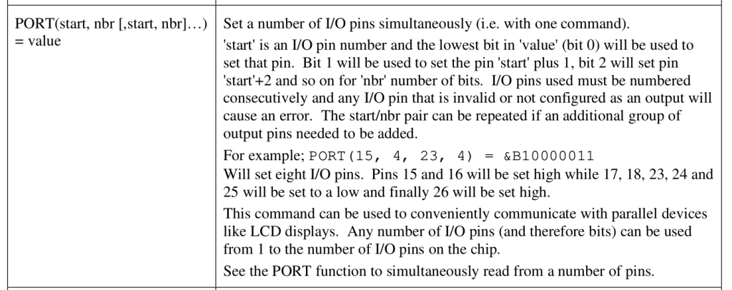 |
||||
| Mixtel90 Guru Joined: 05/10/2019 Location: United KingdomPosts: 8965 |
I think I can see where Vincent is coming from on this, but it's not MMBasic as we currently know it. It's to MMBasic what Circuit Python is to Python 2. A different beast really, built for low level hardware access. You wouldn't normally allow BASIC to have such low level control as it's not really intended to do that. That stuff is supposed to be hidden from the BASIC programmer and "just work". The Commodore computers did but that's only because their BASIC was so unbelievably poor at supporting any hardware at all. Mick Zilog Inside! nascom.info for Nascom & Gemini Preliminary MMBasic docs & my PCB designs |
||||
| vincenthimpe Regular Member Joined: 14/10/2018 Location: United StatesPosts: 86 |
Two issues : 1) That function operates on pin numbers. Not gpio numbers. if i want to set GP0 to GP7 i need to make a complicated definition to skip pin3 and 8(ground) . Pin numbers, in my opinion, are BAD : they tie you to a specific board. if somebody make a different board with different pin allocation nothing works anymore. IO should always be referred by using the processors pin name, not the boards pin name. But that's just my opinion. What do i know ? 2) looking at the C code of the interpreter the pin operations are sequential. They do not change at the same time but one after another. It's essentially a loop that scans through the list. This makes the actual output glitchy. if you go from 0000 to 1111 you get 0001 0011 0111 on the pins before you hit 1111. it gets worse when you go from a random pattern to another random pattern. Every bit flip produces an intermediary state. The same for reading the port. The port is being scanned bit by bit. If you are trying to sample parallel inputs you can get wrong states if the inputs change during the scan. Let's say you want to make a simple logic analyser: if the data changes during the scan you get false information by using the PORT function. It is not a true parallel read/ write. My GPIO library is a true parallel read and write since it accesses the SIO registers directly. The inputs are sampled and stored into the input register in one clock cycle. the only exception is on the 2350 where the bottom 31 bits are synchronous with each other, and 31..47 requires another bus cycle. This is due to the AMBA bus in the processor being only 32 bit. No way around that. But that's fine. At least there are 32 bits that work in parallel. Footnote added 2025-05-10 09:41 by vincenthimpe Edit. V6.x performs the IO differently. it looks like it is no longer sequential now. |
||||
| matherp Guru Joined: 11/12/2012 Location: United KingdomPosts: 11645 |
Not true - try it. Not true - they are all set simultaneously The same for reading the port. The port is being scanned bit by bit. Also not true. What source are you looking at. Clearly not the one on github. Please don't post falsehoods that can confuse others |
||||
| vincenthimpe Regular Member Joined: 14/10/2018 Location: United StatesPosts: 86 |
The manual could use some clarification ... in external.c : while(nbr) { if(!code)pin=codemap(pincode); else pin=pincode; // PIntComma(pin); if(IsInvalidPin(pin) || !(ExtCurrentConfig[pin] == EXT_DIG_OUT )) error("Invalid output pin"); ExtSet(pin, value & 1); value >>= 1; nbr--; pincode++; } This looks like you are walking the given map and, when a pin is valid as output then calling 'extset' with the masked value for the pin . The pins are set one by one in a loop, not as a single transfer. -edit- Apologies. i blew away my copy of the source and pulled a fresh copy from github. Looks like i had an old version . 5.7 6.x has this routine changed. So it is parallel now. Edited 2025-05-10 09:39 by vincenthimpe |
||||
| Page 1 of 2 |
|||||
| The Back Shed's forum code is written, and hosted, in Australia. | © JAQ Software 2026 |
