
|
|
Forum Index : Microcontroller and PC projects : vga working now need resistors wondering is test program for colors
| Author | Message | ||||
| tenij000 Senior Member Joined: 30/05/2025 Location: NetherlandsPosts: 107 |
  is there a program to test te colors |
||||
| stanleyella Guru Joined: 25/06/2022 Location: United KingdomPosts: 2807 |
 |
||||
| stanleyella Guru Joined: 25/06/2022 Location: United KingdomPosts: 2807 |
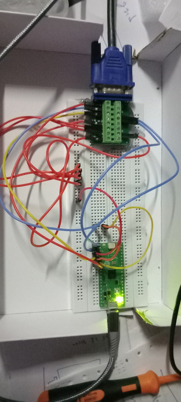
I got a breakout board like that and hdmi the same . wiring vga is a pain 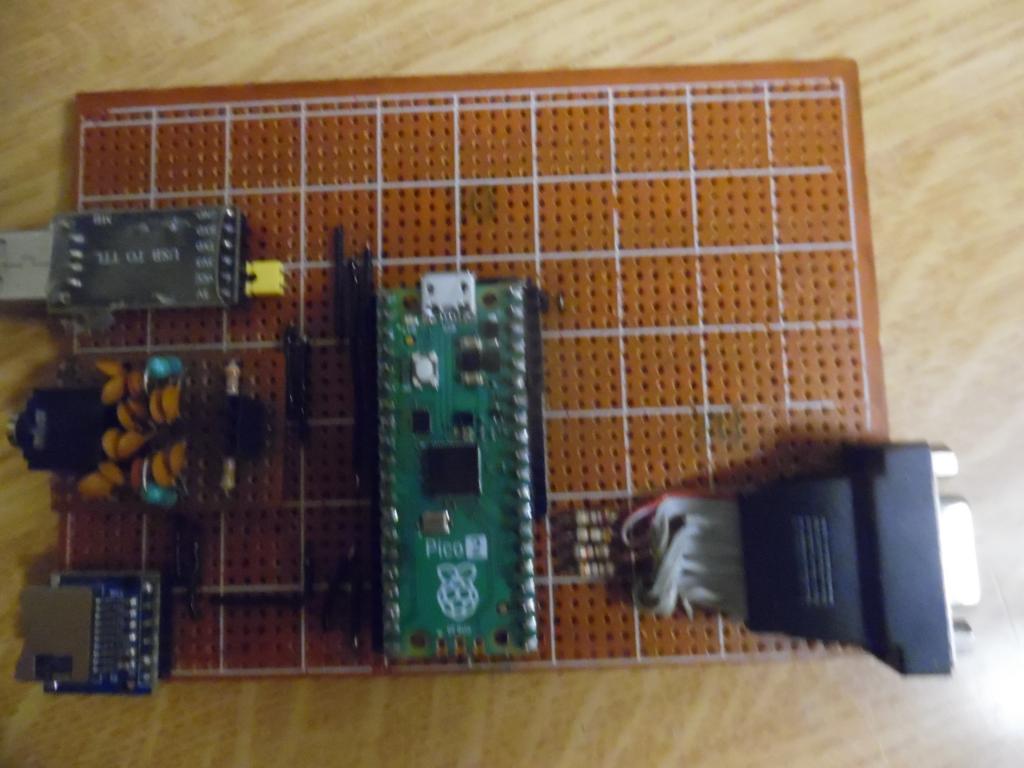 |
||||
| phil99 Guru Joined: 11/02/2018 Location: AustraliaPosts: 3321 |
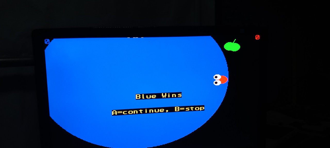
Dim integer w = MM.HRES \ 16, h = MM.VRES, b, g, r, n=0 For b = 0 To 1 For g = 0 To 3 For r = 0 To 1 Box n*w,0,w,h,,, RGB(r*255,g*64,b*255) Print w,h,n,r,g,b,RGB(r*255,g*64,b*255) Inc n Next Next Next End Edited 2025-07-01 08:38 by phil99 |
||||
| tenij000 Senior Member Joined: 30/05/2025 Location: NetherlandsPosts: 107 |
if figure out how find vga connector and footprint that match gone try to make it more smoother Edited 2025-07-01 08:38 by tenij000 |
||||
| stanleyella Guru Joined: 25/06/2022 Location: United KingdomPosts: 2807 |
the manual resistors match the vga colours. have I got wots this is about wrong? |
||||
| phil99 Guru Joined: 11/02/2018 Location: AustraliaPosts: 3321 |
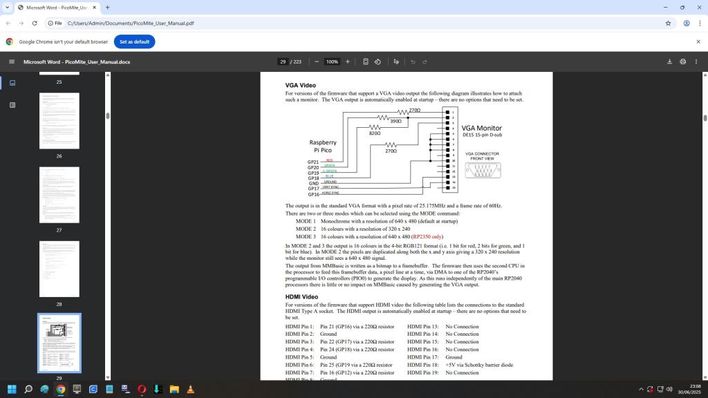
Your picture shows the Pico pins connected directly to the VGA socket. That will overload the Pico and may damage it. The resistors are needed to limit the current. |
||||
| tenij000 Senior Member Joined: 30/05/2025 Location: NetherlandsPosts: 107 |
ok |
||||
| Mixtel90 Guru Joined: 05/10/2019 Location: United KingdomPosts: 8965 |
As Phil says, the resistors are needed to limit the current, but they do more than that. They act as a resistive mixer for green, allowing up to three green levels plus off. The four "colour" pins then act as a binary value to give 15 colours plus black. Mick Zilog Inside! nascom.info for Nascom & Gemini Preliminary MMBasic docs & my PCB designs |
||||
Grogster Admin Group Joined: 31/12/2012 Location: New ZealandPosts: 9995 |
Agreed. The resistors are there for a reason.   Why? Analog VGA is much more forgiving then even SLOW speed HDMI. MHOO....(my humble opinion only) Smoke makes things work. When the smoke gets out, it stops! |
||||
| Mixtel90 Guru Joined: 05/10/2019 Location: United KingdomPosts: 8965 |
I've no problems with either. :) Half the time I only use the console anyway. The Adafruit breakout board makes DVI/HDMI very easy. It uses two more GPIO pins than VGA but it's far more flexible. In my experience the HDMI wiring isn't always critical. We aren't pushing the HDMI system anywhere close to what it can handle. VGA is equally easy if you use a breakout board, just four resistors. I made my own by hot gluing a VGA connector upside down onto padboard and put the resistors from pads up to the VGA pins. It's ugly but it works fine. :) You can also run VGA over CAT5 so some very cheap and reasonably flexible leads are available. :)  It's more hassle remembering which firmware I loaded... :( Mick Zilog Inside! nascom.info for Nascom & Gemini Preliminary MMBasic docs & my PCB designs |
||||
| Martin H. Guru Joined: 04/06/2022 Location: GermanyPosts: 1485 |
Mode 2 Dim Col(15) As Integer :Restore colors:For f=1 To 15:Read Col(f):Next CLS :For f=0 to 15:read c$ Box 0,f*15,320,16,,Col(f),Col(f) Text 32,f*15,c$ next colors: '--Colorscheme accordung to Spritecolors Data RGB(BLUE),RGB(GREEN),RGB(CYAN),RGB(RED) Data RGB(MAGENTA),RGB(YELLOW),RGB(WHITE),RGB(MYRTLE) Data RGB(COBALT) ,RGB(MIDGREEN),RGB(CERULEAN),RGB(RUST) Data RGB(FUCHSIA),RGB(BROWN),RGB(LILAC) Data "BLACK","BLUE","GREEN","CYAN","RED" Data "MAGENTA","YELLOW","WHITE","MYRTLE" Data "COBALT" ,"MIDGREEN","CERULEAN","RUST" Data "FUCHSIA","BROWN","LILAC" 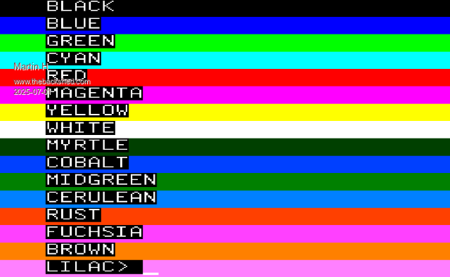 Edited 2025-07-01 20:30 by Martin H. 'no comment |
||||
| javavi Guru Joined: 01/10/2023 Location: UkrainePosts: 568 |
@tenij000 For the VGA video output of the PicoMite, you can make a resistor switch to switch between two 16-color palettes. I think that even the Windows palette is even more applicable in practice due to the two shades of gray.   |
||||
| stanleyella Guru Joined: 25/06/2022 Location: United KingdomPosts: 2807 |
it's just not strip board friendly. my first vga when a multi turn pot was in the circuit but I posted adjusting it did nothing and it was removed. cheap vga lead from ebay just for the sockets. 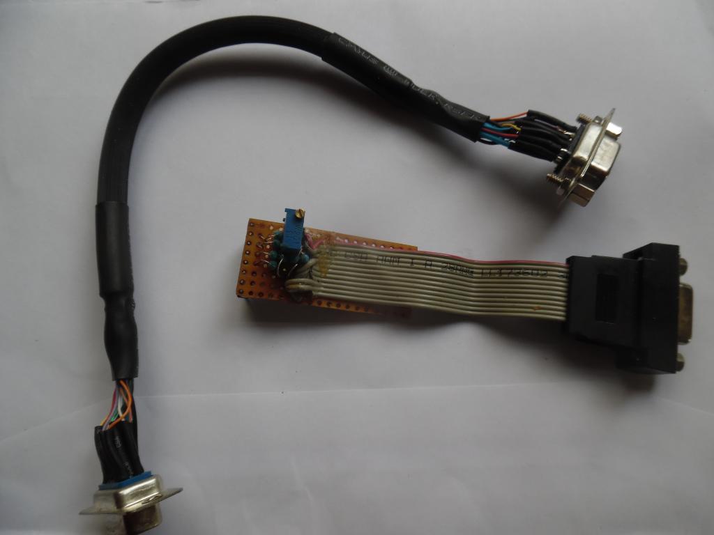 |
||||
| Mixtel90 Guru Joined: 05/10/2019 Location: United KingdomPosts: 8965 |
Interesting, Javavi. That's not the same diagram that you posted last time. R6 went to G1, not G0. It looks like the correction fairy has been round to visit. :) A couple of things I don't like about the Windows colours is that 5 & C are very similar and orange is missing. It certainly has its uses though. . Edited 2025-07-02 01:30 by Mixtel90 Mick Zilog Inside! nascom.info for Nascom & Gemini Preliminary MMBasic docs & my PCB designs |
||||
| javavi Guru Joined: 01/10/2023 Location: UkrainePosts: 568 |
Hi Mick, Yes, there was a mistake in the previous diagram, I corrected the diagram here. And also corrected color 5 in the color chart, this seems to be correct: 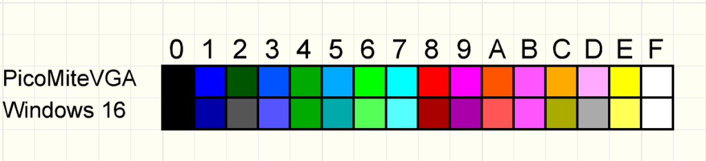 |
||||
| Mixtel90 Guru Joined: 05/10/2019 Location: United KingdomPosts: 8965 |
Thanks. That looks a lot better. :) I'm just using your switching scheme on my Multi2 design. :) Mick Zilog Inside! nascom.info for Nascom & Gemini Preliminary MMBasic docs & my PCB designs |
||||
| The Back Shed's forum code is written, and hosted, in Australia. | © JAQ Software 2026 |
