
|
|
Forum Index : Microcontroller and PC projects : 3.2" ILI9341 SPI LCD has changed
| Author | Message | ||||
| Volhout Guru Joined: 05/03/2018 Location: NetherlandsPosts: 5994 |
For my second Game*Mite I ordered a new 3.2" ILI9341 SPI LCD. I like the 2.8" but the 3.2 was just a bit bigger, and better for my old eyes. I received the LCD to day, and at first glance it looked identical to the old one. But... the SD card would not work. The board has a different layout. And I applied some fixes to make it work. - There is a low drop regulator on the board. This regulator does not have any decoupling capacitors (there is not even a footprint for these). I decided to bypass the regulator (solder blob), and added a decoupling capacitor (1uF ceramic) directly at the SD card pins. - There are no resistors in the SCK, MOSI and CS lines for the SD card. I did cut the lines and added these. Some may debate whether these are needed, but I have had reliable operation with these resistors in previous boards, so I put them in (they alter wave form and setup and hold timing). - the transistor that drives the backlight has a base resistor, but the collector resistor is shorted (small trace between the pads of the footprint). This means that any current limitation in the backlight is depending on the gain and saturation of the transistor. For now I left it as is, but I may make a change later on. So just a heads up for those who still buy ILI9341 displays. These changes may also pop up in the future on 2.8" and 2.4" displays as a form of cost reduction. And you may wonder why they don't work. Regards, Volhout PicomiteVGA PETSCII ROBOTS |
||||
| ville56 Guru Joined: 08/06/2022 Location: AustriaPosts: 550 |
Thanks for the info, Vollhout. Can you please attach a picture of the component side so one can identify the display as one of these "optimized" parts more easily. Thanks, Gerald 73 de OE1HGA, Gerald |
||||
| stanleyella Guru Joined: 25/06/2022 Location: United KingdomPosts: 2807 |
they all work the same for me, I made my board take both sizes and prefer the bigger one... same res ... but larger 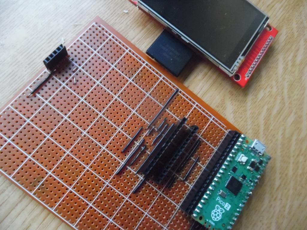 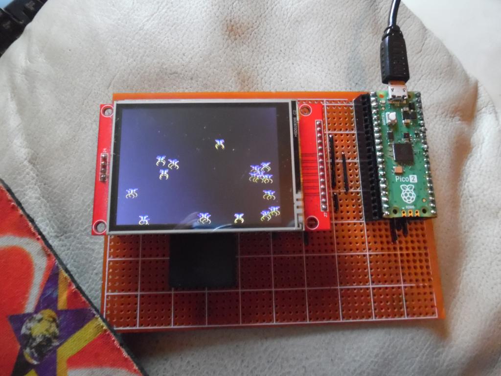 |
||||
| Volhout Guru Joined: 05/03/2018 Location: NetherlandsPosts: 5994 |
Hi Gerald, I don't have a picture of the old one. But this is the new one with my modifications. 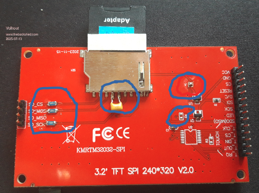 Volhout PicomiteVGA PETSCII ROBOTS |
||||
| phil99 Guru Joined: 11/02/2018 Location: AustraliaPosts: 3321 |
In the past to improve reliability people have been shorting out the resistors you added. I have both types and they are both reliable. My guess is the resistors were intended to protect the SD card if used with an Arduino's 5V logic. |
||||
| stanleyella Guru Joined: 25/06/2022 Location: United KingdomPosts: 2807 |
yeah you needed a logic level converter for arduino and ili9341 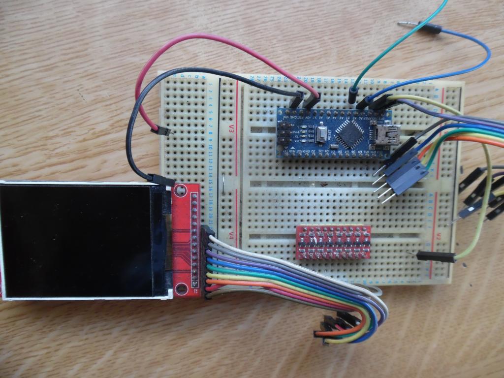 |
||||
| The Back Shed's forum code is written, and hosted, in Australia. | © JAQ Software 2026 |
