
|
|
Forum Index : Microcontroller and PC projects : Ok, now I am a fan of HDMI + Gerber + RGB332 palette for PS
| Author | Message | ||||
| Amnesie Guru Joined: 30/06/2020 Location: GermanyPosts: 763 |
After the big problems with HDMI not working at all on my original Raspberry Pi monitor, I gave it a second chance and designed a new PCB. There are (as far as I know) only HDMI USB variants of the reference design. Due to my problems with the slow USB problems (now fixed by Peter! - thank you) and for the sake of simplicity, I made my PCB for PS/2 keyboard / PS/2 mouse. If you are interested, just download the Gerbers. But to my suprise, the resolution of 848 in mode 5 with 256 colors is quite amazing. For the ones who use Photoshop, I created a RGB332 color palette, you only need to import it and load the palette with your own image, Photoshop asks for dithering and you can choose. Here is my result: 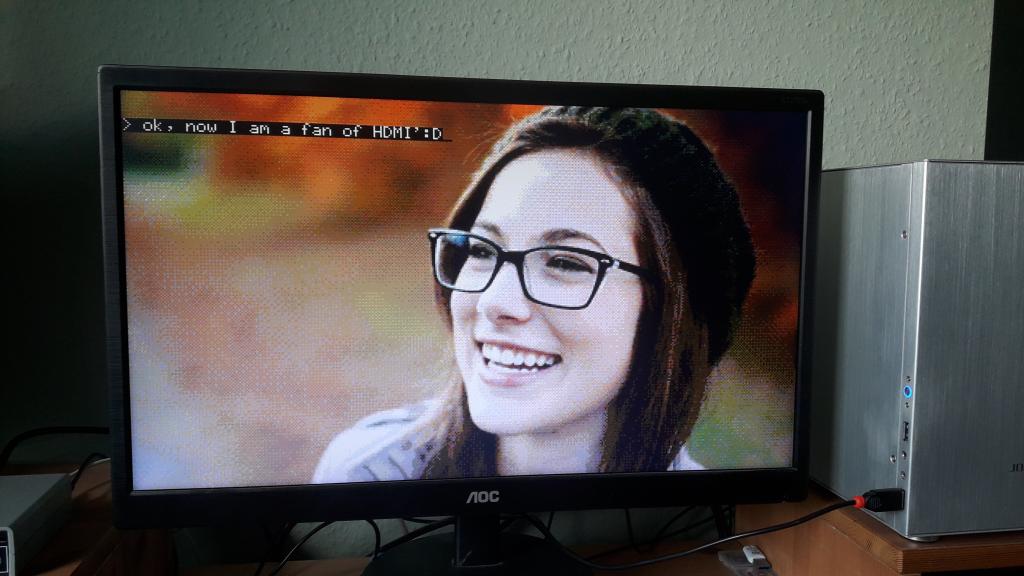 in my zip folder you find: - original image (downsized) - converted & dithered RGB332 image - Photoshop RGB332 palette frau_rgb332.zip In case you want my PCB, here is the Gerber: Gerber_gainta_picoMiteHDMI_ps2_2025-07-30.zip 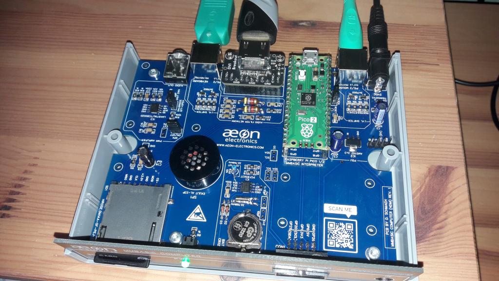 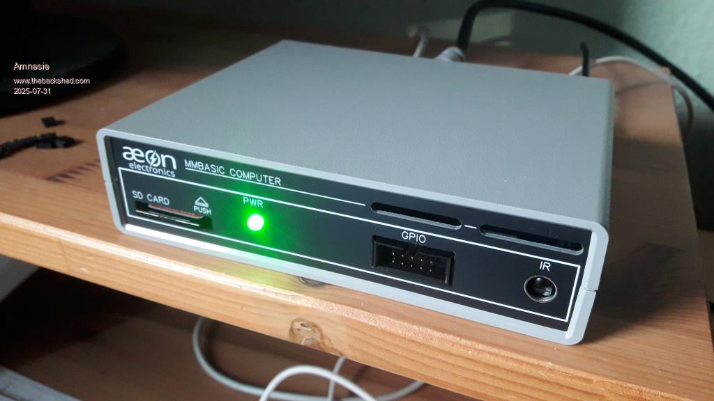 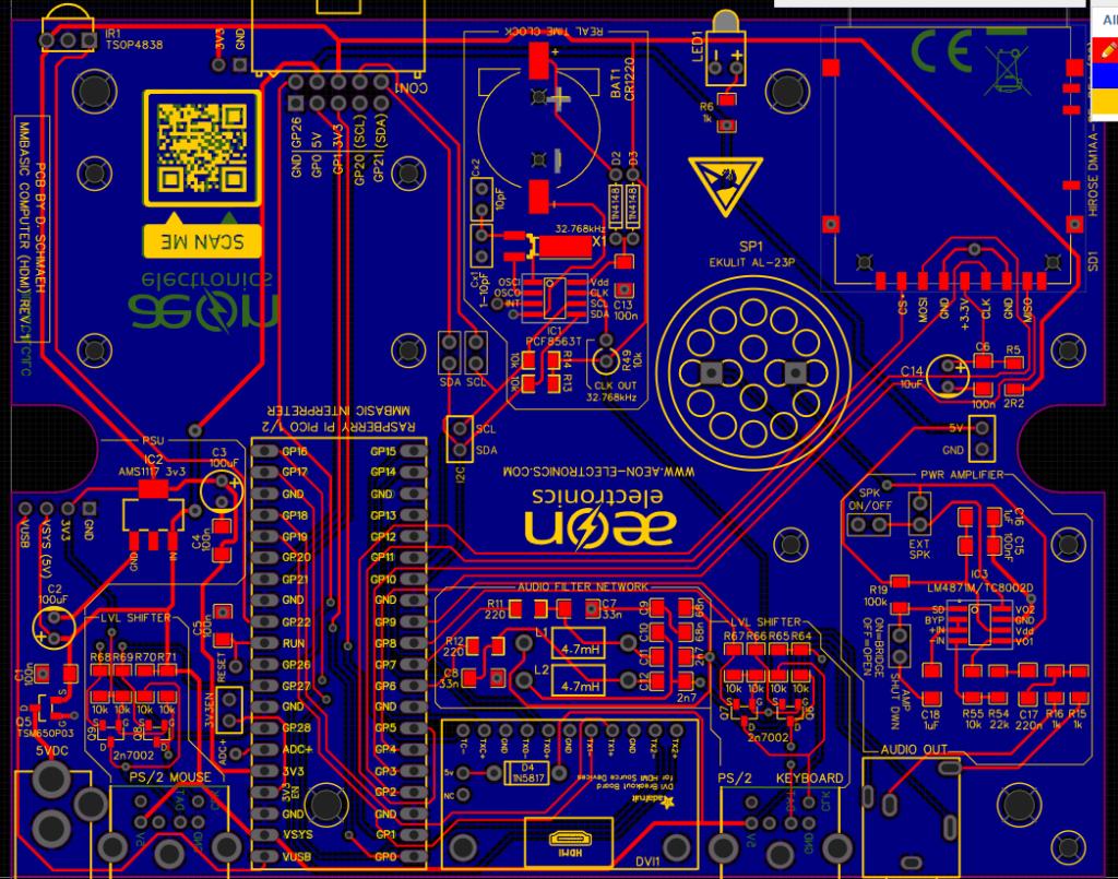 Pinout: 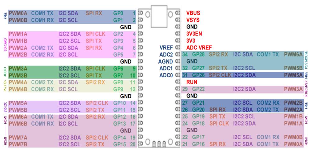 Maybe it is useful for someone  Greetings Daniel Edited 2025-07-31 03:59 by Amnesie |
||||
| Plasmamac Guru Joined: 31/01/2019 Location: GermanyPosts: 620 |
Thx Daniel Plasma |
||||
| lizby Guru Joined: 17/05/2016 Location: United StatesPosts: 3816 |
Excellent work all around. PicoMite, Armmite F4, SensorKits, MMBasic Hardware, Games, etc. on FOTS |
||||
| Mixtel90 Guru Joined: 05/10/2019 Location: United KingdomPosts: 8965 |
t was an interesting decision to put the HSTX signal connections on the opposite side and end of the PicoMite. Was there a particular reason for this? In the past I've usually attempted to keep them as short as possible. That looks like the CMM2 case. It's a bit of a pig to work with, I've found. No matter what you do the PCB supports are in the wrong place! Nice board though. :) Mick Zilog Inside! nascom.info for Nascom & Gemini Preliminary MMBasic docs & my PCB designs |
||||
| Amnesie Guru Joined: 30/06/2020 Location: GermanyPosts: 763 |
Hello, I've read a lot about it and came to the conclusion that (after my breadboard attemps - which worked fine, even with LONG cables 30cm!) I don't do track-length matching. This is a rabbit hole. If you really want to do it right, that means impedance matching, track length, correct GND routing (via are a no-no!) then you can't even use the Adafruit Adaptor board, this is (when it comes to trackrouting) also not ideal. The main reason was: I don't like to have the connectors on the places they are on the reference design. It is not practical for me. Before I designed the PCB I tested various breadboard calbe positions and lenghts and wasn't able to get a bad signal or huge interference. We have seen some people on this forum, who have used even perf-board with HDMI... (Stan?!) As said in an early post; only monitor which doesn't work was the Raspberry Pi original monitor. I have sent it back, so I can't test it again with it. But all other monitors and TVs work with breadboard and my PCB approach. Maybe the HDMI signal is more robust, because of the low signal clock ... I mean it isn't much data to be transfered. But I have absolutly no idea - this is too complex for my understanding.  P.S. yes it is the CMM2 case - I like it! Greetings Daniel Edited 2025-08-01 01:07 by Amnesie |
||||
| The Back Shed's forum code is written, and hosted, in Australia. | © JAQ Software 2026 |
