
|
|
Forum Index : Microcontroller and PC projects : STM32 Blupill and / or Pico
| Page 1 of 2 |
|||||
| Author | Message | ||||
| stef123 Senior Member Joined: 25/09/2024 Location: United KingdomPosts: 105 |
Hi, just a question apart from Picomite - is it possible that the Arduino Wire Library has still issues in terms of acting as an I2C Slave on the STM32F103C8T6 (Bluepill) or Pico? Acting as a Slave works fine on PicoMite, but as the entire construction controls an BLDC Motor by using a SimonK ESC Controller, i need a finer PWM Duty Cycle granularity. Also the I2C Master, which i cannot reprogram, does eventually put the MCU and the ESC under power whenever access to the I2C slave is needed, so i need a pretty fast MCU power up sequence. If the master doesnt get a response in time, it will reboot. This and the finer PWM granularity is the reason why i´d like to rather use Arduino, or even bare C++. But as being said, Arduinoś Wire Lib seems to have issues here and there.... |
||||
| Mixtel90 Guru Joined: 05/10/2019 Location: United KingdomPosts: 8965 |
The boot up sequence is the result of running an interpreter on the chip. It has a lot of housekeeping to do before it passes control over to the user. It doesn't matter what the chip is you'll always have that problem. A compiler would give you faster startup as the processor would be running bare metal code right from the start. I2C is supposed to be 2-way and the master should be waiting for the slave to enable the I2C bus before it starts sending commands. That's bad programming and it sounds like you can't do anything about it! Of course, it might be waiting but the timeout delay is too short so it reboots. Do you need PWM specifically or a DAC? The latter might be better from a resolution point of view. Mick Zilog Inside! nascom.info for Nascom & Gemini Preliminary MMBasic docs & my PCB designs |
||||
| stef123 Senior Member Joined: 25/09/2024 Location: United KingdomPosts: 105 |
I knww that the startup Time of Picomite could cause an issue, so i wanted to go to "Bare Metal" in this case. Meanwhile i got it mostly working using the Wire library and Arduino. Yes, PWM is absolutely necessary in this case because the ESC controller needs a pretty stable PWM input. Its not about the PWM frequency, which can be between 50 to 460 HZ (but stable anyway), but the Duty Cycle. Idk the exact resolution of the PWM channels of the Pico, but i have to use duty cycles between 1000 and 1600 Microseconds. The goal of this construction is an Motor PCB Replacement for a Neato Robot Vacuum, which has failed (including the Motor). As long as the Motor PCB was working, i was able to capture the I2C Stream being sent from the Vac's Mainboard to this PCB and back from the Motor PCB to the Host, but as it turns out, it was not as easy as it sounds like, because the Robot Vac transmits single i2c bytes in combination with an i2C restart in order to keep the communication with the motor pcb alive and the Motor PCB sends back some single bytes back (about 75 possible differnet single bytes) There are two byte i2c commands aswell being sent from the host, which eventually control the speed of the motor and set the motor on/off, without a response to the host. In addition, the Host wants information about RPM and Current being drawn from the Motor, this has to be packed somwwhere else in the single byte responses. They have to match a certain pattern, which is currently being held in a table (in fact the single byte responses which i was able to capture). If this doesnt match, the Robot will immediately reset. Currently i am Stuck at the point where the Host turns on the Motor, then wants a 1 byte Response as being explained, but adds an unusual long delay (80 msec) before finally reading the byte, which was written back by my Controller - and then everything stalls. I2C communication breaks up completely (its not the only device on the I2C Bus). Host resets. So i was not sure if this was/is an "Wire" Library/PWM/both-issue (probably communication timeout) or something else. As long no PWM is being involved, everything is fine. As soon PWM comes in and the Motor turns on (revving up slowly to the target value in order to keep a linear current draw), this will raise the issue i have explained. I guess its not power related (Caps have been added for security). My MCU is powered from the ESCs extra 5 Volt output, which in turn is fed by a CV/CC Limiter at 7.4 Volts and a few Amps. The CC/CV DC-DC Converter is being connected to the Main PCB (a FET does there the Power on/off function to the Motor PCB) and because the original Motor PCB was fed with +-15 Volts and the original BLDC Motor was drawing way more current than the small, but way more efficient Turbine being used now, i have to put Voltage and Current down. So this is why i think that it cannot be power related. According to the onbaord LED of the Pico, which i programmed to blink each half second, the MCU itself is active all the time, even when the Main CPU on the host gets unresponsive. The Host itself can be accessed via USB CDC and various test functions are presented there. Have to turn the Analyzer back on.... Edited 2025-09-22 09:45 by stef123 |
||||
| stef123 Senior Member Joined: 25/09/2024 Location: United KingdomPosts: 105 |
Since the Host now started to stall even when the PWM functionality was fully removed from the Arduino Code, it must be an issue related to the Arduino Wire Library in Slave Mode. Bluepill didnt do anything at all - not related to Pullups, port settings etc), even an ATMEGA1284P didnt work properly as a slave. The Pico with Arduino Code did somehow work, but eventually stalled. And an I2C communication stall leeds to a Host Reset. A Picomite program which does the same Job (but currently without PWM) does a pretty good Job, responds all the Time without hanging up, but as being said, the Picomite PWM functionality unfortunaly doesnt currently work for me. I also haven't checked so far if Picomite starts up at a sufficient speed. Maybe i have to modify the PM sources somehow. If Hardware PWM is being used - which i suppose - it should not have an impact on execution speed. |
||||
| PhenixRising Guru Joined: 07/11/2023 Location: United KingdomPosts: 2005 |
I am notoriously bad at understanding what is being asked  But you are aware that the PWM accepts fractions of %, right? Seems to me that at that frequency, you should have resolution (granularity) in spades. Edit: I once made the mistake of assuming that the single digit decimal fraction (shown in the manual) was the limit but it is isn't. Edited 2025-09-22 20:18 by PhenixRising |
||||
| stef123 Senior Member Joined: 25/09/2024 Location: United KingdomPosts: 105 |
Aha -thats what i didnt consider - great! This makes things a lot more easier - indeed, Manual says something about non-fractional Numbers between -100 and +100, so i thought that decimal point values were not allowed. Thanks for the hint - i appreciate it! Stef Edited 2025-09-22 21:48 by stef123 |
||||
| PhenixRising Guru Joined: 07/11/2023 Location: United KingdomPosts: 2005 |
Yeah, I assume that the decimal point, shown in the manual, merely indicates that it takes a float. I took it literally to be only one decimal which had me believing that resolution was limited to an effective +/- 1000. It was a relief to find that this isn't the case  Edited 2025-09-22 21:56 by PhenixRising |
||||
| stef123 Senior Member Joined: 25/09/2024 Location: United KingdomPosts: 105 |
You are right, i've overseen that.... Currently i have to work with Duty Cycles from 1.350 to 1.420 in steps of 0.001, in order to get full range speed control of the ESC Controller. The Motor itself can rev up to 80.000 RPM, way more than an usual A2212 for example Drones. |
||||
| PhenixRising Guru Joined: 07/11/2023 Location: United KingdomPosts: 2005 |
I'd like to see how that performs. I totally ignore conventional "wisdom" when I see potential. I have been looking at these ESCs with a view to closing the loop on a brushless motor. The PicoMite has PID and we are able to read encoders at high speed via PIO. There is a motion controller IC LM629, that is widely used in industrial controls but it only has 8-bit motor command (+/- 127) and is limited to 1M quadrature counts/sec. The PicoMite not only out-performs it but it has time to spare to run sequence code and of course lots of I/O. The LM629 can only generate a trapezoidal velocity profile whereas I also have s-curve (much smoother). Slight difference in price, also 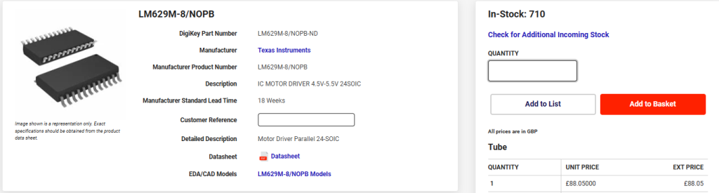 At the moment, I drive brush-type motors but I think I'll grab one of those ESCs and a BLM to see what I can do. Please keep us updated  |
||||
| stef123 Senior Member Joined: 25/09/2024 Location: United KingdomPosts: 105 |
The good thing about the out-of-the-Box ESC driver Modules is that they usually do not need Encoders on the Motor at all, because they use Back-EMF in order to get the Motor Position and Rotation direction, so by that the RPM (internally). Thats because in BLDC Motors, one Coil out of three in total is not driven at the same time. So this inactive Coil is taken to measure Power/current when being magnetized by the Rotor. This Value is eventually going into the Microcontroller, which gets by that an absolute precise Information about the Speed / rotation direction and can act accordingly by varying the PWM Duty Cycles and PWM Speeds, which in turn control a Gate driver, which in turn controls the H-Bridges. Of course the magnetic field is rotating inside the Motor, so the active and inactive coils are switching. So in total three PWM Channels, three ADC channels (or some external circutry) and extra pins would be needed, if someone would have the need to make its own BLDC Controller - but its not worth the hassle. Note that BLDC Motors are not suitable for Servo/Stepper-like applications, the Coils and Motor driver would immediate go nuts when permanently powered and heat up pretty much. So cooling of a BLDC Motor is absolute necessary. I have a 12A ESC, runnning from 7.4 to 14.8 Volts, providing up to 12A Motor Current and delivers extra 5V /3A Power output for attaching an MCU. As being said, it needs a single PWM input - like most other ESC Controllers do - for Speed Control. Cost was about €8, so its not worth to think about something self-built; at least 6 H-Bridges would be needed and some other circutry, exluding the MCU, which manages all. There are a lot of other BLDC Motor controllers out there with way more Current potential. BLDC Motors can be pretty strong at a relative low Power consumption, in comparison to Brush Motors - and operate smoother. By the way, even PC Fans are BLDC Motors with integrated BLDC Controllers, but of course entirely self-managing. Edited 2025-09-23 03:21 by stef123 |
||||
| Volhout Guru Joined: 05/03/2018 Location: NetherlandsPosts: 5994 |
stef, The ESC's used to drive propellers are not suited for anything else. They only return the rotor position by powering the stator coils, inherently causing rotation. That is not useful in industial systems. These use hall sensors to determine the rotor position when it is static. Volhout PicomiteVGA PETSCII ROBOTS |
||||
| PhenixRising Guru Joined: 07/11/2023 Location: United KingdomPosts: 2005 |
Yes, I'm only talking velocity and position control. The unknown is the performance of the ESC's FOC (field oriented control). It might be rubbish at low speed. |
||||
| stef123 Senior Member Joined: 25/09/2024 Location: United KingdomPosts: 105 |
Indeed, i didnt consider industrial Applications, sorry about that, I thought that we are talking about low end applications in the same manner, like low-end ESC/BLDCs without encoder are privately used in high speed applications, i am not working in the industrial field. Phenix, may i ask for what type of machinery you consider to switch from brush motors to BLDCs? |
||||
| PhenixRising Guru Joined: 07/11/2023 Location: United KingdomPosts: 2005 |
Hi Stef, I have been using industrial BLDCs since 1993. I only have brush-type motors (with encoders) on my desktop test-rig. I have no intention of doing anything with the cheap ESCs at this point because I don't use anything smaller than 700W and I go all the way up to 100HP AC Vector Drive (aka: FOC) I am just curious to see how they behave with a PID and encoder feedback. My standard encoder is 4096-line which after quadrature decode gives 16,384 counts. So I can achieve a position of 360°/16,384. But for my machines, I use industrial drives and motors. My specialty is CNC tube forming. I was the founder of what became the #1 manufacturer of CNC tube forming machines in North America. I discovered FOC (Vector Drive) in 1993 when it was in its infancy and it was a huge breakthrough because it enabled me to create 100% electric tube forming machines when US automotive was demanding greater speed/accuracy. What used to be exhaust pipes became "emission control systems" with all kinds of sensors and super-tight tolerances. I ended-up with at least 70% of the market. I also designed and built the one and only machine that produces the entire Corvette chassis. It was the first machine with 100HP Vector Drive.  |
||||
| stef123 Senior Member Joined: 25/09/2024 Location: United KingdomPosts: 105 |
Wow, respect |
||||
| PhenixRising Guru Joined: 07/11/2023 Location: United KingdomPosts: 2005 |
The thing is that; I am qualified and experienced enough to know that MMBasic is capable of much more than retro gaming much more but I'm alone on this soap box I have a combo of Android tablet, connected via Bluetooth to PicoMites and the end result is superior performance to the big name BS and the problem of built in obsolescence is eliminated. Just got back from a customer in Openshaw. Their Siemens touchscreen system died, three weeks ago and can't be fixed. Their customer is screaming for parts. They have my tablet control on other machines and they wondered if I could simply replace the Siemens HMI with a tablet 🤣😂 No I would have to throw out the entire Siemens system because it all runs on the godawful Profibus. |
||||
| stef123 Senior Member Joined: 25/09/2024 Location: United KingdomPosts: 105 |
Meanwhile i got everything working - "unfortunaly" in C++, but no chance to do it with PicoMite. Altrough i was able to do the same Job in a far easier manner by using PM, its startup Time was simply too long, as being predicted. But it was challenging anyway. Sure, ESCs are simple to handle, but i have must made an calibration mistake which eventually resulted in way smaller Duty Cycle expectations as being normally expected -136 to 142 uSec(!) for a speed setting from 0 to 6 (the Program in the Vacuum Robot does only transfer 0 to 6 for speed settings, not RPMS or anything else) - instead of 1000-2000 uSec. That worked with Picomite - and the ESC handled it pretty well, but not C++, where i used a Base of 1000 to 2000 uSec. But even setting it in the expected range resulted in Chaos. I tried several times to recalibrate the ESC, but nothing really worked, until a few hours ago. So finally i can grab everything, put it into the Robot Vac -before that i have to make some housing for the Turbine with my 3D Printer - put it in and hopefully i have never to touch it again. If you -know- how the communciation between I2C Master and Slave looks like - what the Master sends and what the Master expects - it would have been an relative easy task. But if you get only get dozens of bytes without really knowing what they do, or how valid response should look like, you will get headaches. Naturally i had no "official" access to the Robot Vacs Firmware, altrough i tried to disassemble it by using a Firmware upgrade file - thankfully not Secured.. But the Vac is running on a small Linux, no chance to find out whats Part of the OS and whats Part of the Program and virtually no one can convert Assembly Code of this Sort and Size back to C++ Code, even not with Radare2 or Ghidra. |
||||
| stef123 Senior Member Joined: 25/09/2024 Location: United KingdomPosts: 105 |
I use Webmites aswell. Latest construction is some sort of autonomous Power Delivery system with integrated Solar Charger, LiFePo Battery and DC-AC Inverter, some Relais and a Webmite, accessible via Telnet. Of course i have taken the guts out of an regular Solar Charger and Inverter and placed them into the Box. The PCB with the Webmite chooses which Solar Panel (Balcony 1, Balcony 2 on opposite location of the building) should be routed to the Solar charger at a certain Date/Time (depends on the location), Webmite measures the Battery Voltage, if it is over an certain treshold, it switches from Grid to Inverter and vice versa, if the Battery is too low. Some Landlords dont want to have inverters on their house cabling, because Solar Inverters regulary burn down entire houses *cough* , so this is a solution to prevent any discussion. By that i have at any time no Solar Inverters connected to the Grid, but still can use Solar Power. Edited 2025-09-24 03:33 by stef123 |
||||
| PhenixRising Guru Joined: 07/11/2023 Location: United KingdomPosts: 2005 |
No kidding. Are the WebMites proving to be reliable? I haven't gotten the warm and fuzzy about them at this point. |
||||
| stef123 Senior Member Joined: 25/09/2024 Location: United KingdomPosts: 105 |
As far as I can tell, yes—no problems at all. The Solar Box has been running for a couple of months now without needing a restart (even with frequent Telnet access). The cool thing about the Webmites is that you can upload programs either via Telnet or SFTP, and you get full editor access through Telnet. This naturally eliminates the need for a USB connection. If I hadn’t been successful with my BLDC project and C++, I would have gone with a Webmite and installed an on/off switch in the robot’s shell to activate the Webmite whenever the robot needs access to it (i.e., leave it permanently on while cleaning) and turn it off whenever the robot is charging. It runs on Li-Ion batteries, and charging while discharging in parallel isn’t good for them. Why a Webmite - because i want to prevent disassembling the entire Vac again, if i want to change something on the Program - for any reason. I have a second robot without a mainboard here, and one of my plans is to have the Pico W—or even a few of them—play a key role in the whole system. They would control and read the LIDAR, motors, ultrasonic/infrared distance sensors, front and side bumper switches, and also plan and execute the room cleaning. They’d also handle data from an accelerometer and compass, and keep track of the room structure, etc. Alternatively, one Pico (or two) W boards could handle the "mechanical" work, while a Pi Zero 2 W running Linux would handle the "thinking" and decision-making. Naturally, I don’t want to have programming cables connected all the time or walk behind the robot with a laptop while testing and reprogramming it. Programming a robot vacuum isn't like building a simple line follower—it's a pretty tough task. I already have a "half" self-made vacuum running with steppers, but currently it lacks LIDAR, brushes, and any real intelligence. It works, but it’s limited due to the fact that it only uses some ultrasonic and infrared sensors—and it can’t climb, so it can’t handle every situation that might occur (like temporary obstacles or carpets on the floor). That’s where the second mainboard-less vacuum comes in handy, because it already has all the necessary sensors and the ability to climb (sort of - carpets for example, things up to 2cm in height). Edited 2025-09-24 06:15 by stef123 |
||||
| Page 1 of 2 |
|||||
| The Back Shed's forum code is written, and hosted, in Australia. | © JAQ Software 2026 |
