
|
|
Forum Index : Microcontroller and PC projects : PicoBuddy Picomite computer board
| Page 1 of 3 |
|||||
| Author | Message | ||||
| DaveC5 Newbie Joined: 24/09/2025 Location: United KingdomPosts: 40 |
Hi, I'm new to this forum, so thanks for letting me on board. I've been working on a PCB to support the PicoMite boot-to-basic firmware, to come up with a low-cost computer reminiscent of the old 8-bit machines of the late 70s/early 80s. - Low-cost to build. The target was to be able to build from kit for the same price or less as the original ZX81 kit, £49.99. Barring the PCB and the Raspberry Pi Pico itself, the components come to just under £29 to cover a full build with all the options fitted. - Simple to build. The target was to make the build possible with only basic soldering tools and skills, and as uncomplicated to build as I could make it. The components had to be distinct (e.g. resistors should not have similar colour values) and the orientation of polarised components should be strictly controlled on the PCB to aid visual inspection. THP components wherever possible. - Multiple applications. I kept in mind the BBC Micro, which was designed to maximise its “usefulness” in real-world or educational settings. - Multiple power options. - Flexible implementation. Whilst including the additional hardware options implied by the additional functions, the machine should not be reliant on them, so that it can be assembled with a minimal configuration (i.e. keyboard and VGA). - Restrained quirkiness. One of the reasons the old 70’s/80’s machines are remembered with fondness, even championed, by owners is that they each had their own personality. I wanted to have some fun with the design, to add a little productive quirkiness After building a few dev prototype boards, here's the Rev 1.0 setup. There are a couple of typos on the silk-screen still to sort out yet. The board is just shy of 150 mm x 100 mm to fit the old "Eurocard" format, with supports round connectors for strength. I don't have a case for it, but have a couple of ideas in mind, just need to up my CAD skills to realise them. 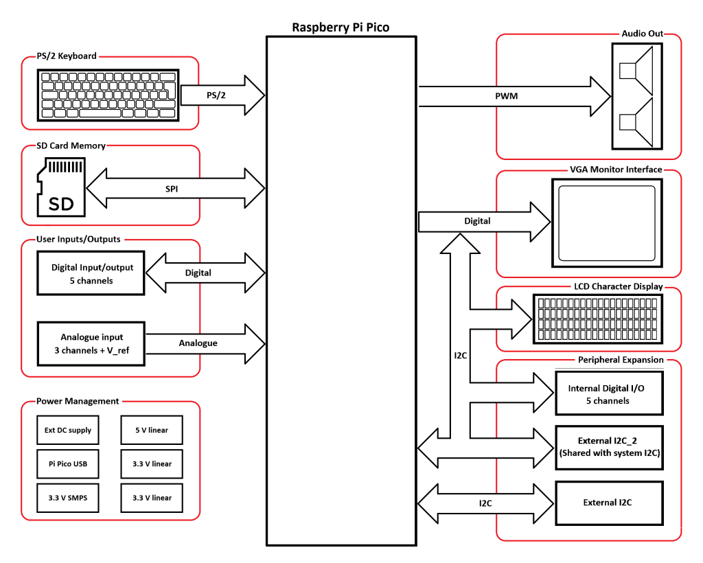 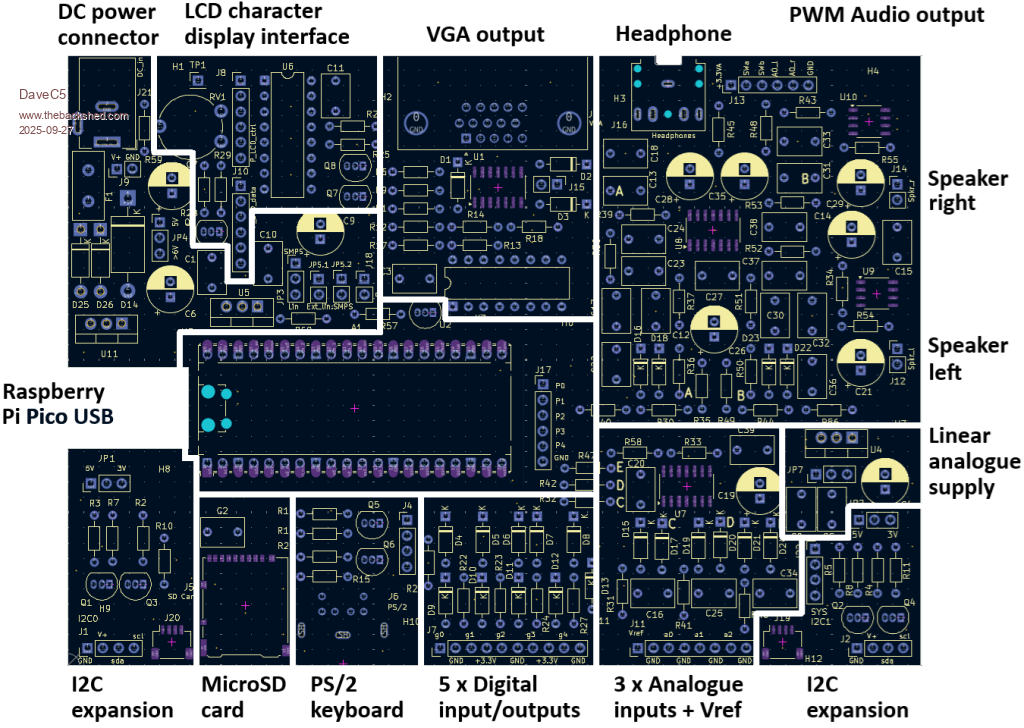 Cheers Dave |
||||
| DaveC5 Newbie Joined: 24/09/2025 Location: United KingdomPosts: 40 |
I should emphasise that the idea was to have something that would be fun and educational to build. Also the "quirks" include: - Palette-Shifter hardware, expands the colour range available to the stock PicoMite VGA - Active filter to the PWM audio output to give good quality audio without using DSP or CODEC devices. - On-board LCD character display interface so that the computer can run with a notifier display (for example) or perhaps in an embedded controller application using a simple button/display interface. None of these additional options rely on alterations being made to the stock PicoMite firmware. They work out-of-the-box, or use simple BASIC routines that can be included in user’s programs to use the Palette Shifter and the LCD interface. Cheers Dave |
||||
| lizby Guru Joined: 17/05/2016 Location: United StatesPosts: 3811 |
Impressive first post. Welcome to the forum. Please post some pics of what you have built so far. PicoMite, Armmite F4, SensorKits, MMBasic Hardware, Games, etc. on FOTS |
||||
| JohnS Guru Joined: 18/11/2011 Location: United KingdomPosts: 4352 |
Watching with interest... John |
||||
| DaveC5 Newbie Joined: 24/09/2025 Location: United KingdomPosts: 40 |
Hi again, Thanks for the interest. Here is a picture of the Rev 1.0 board in action, with some examples of the Palette Shifter doing its thing. With regards to audio, I've found that those larger laptop-style speakers give really nice results, when running the 3.3V analogue internals from the onboard linear regulator supply. 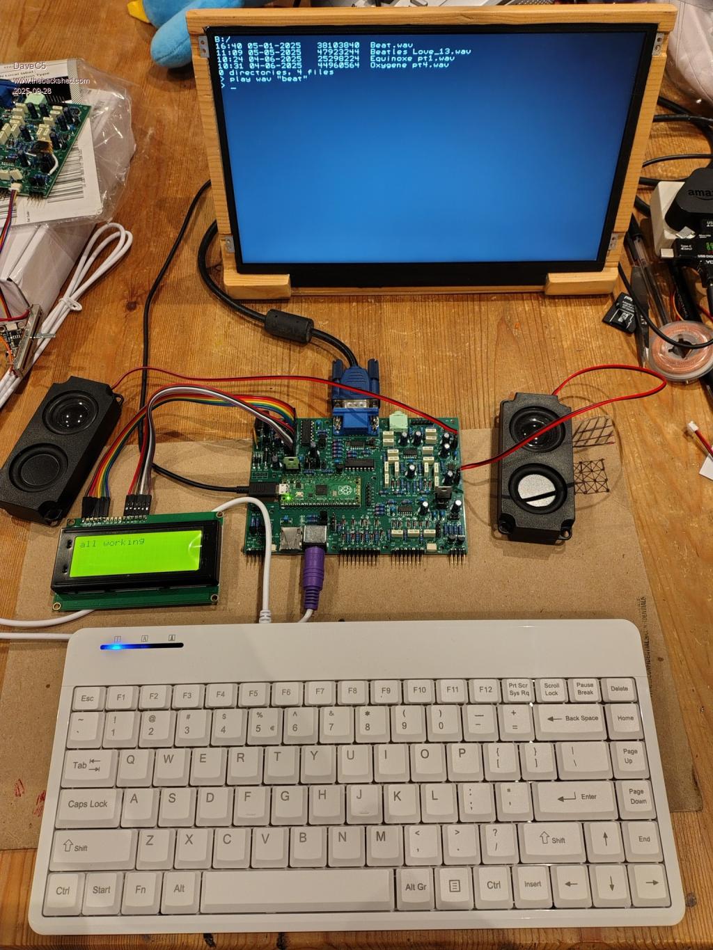 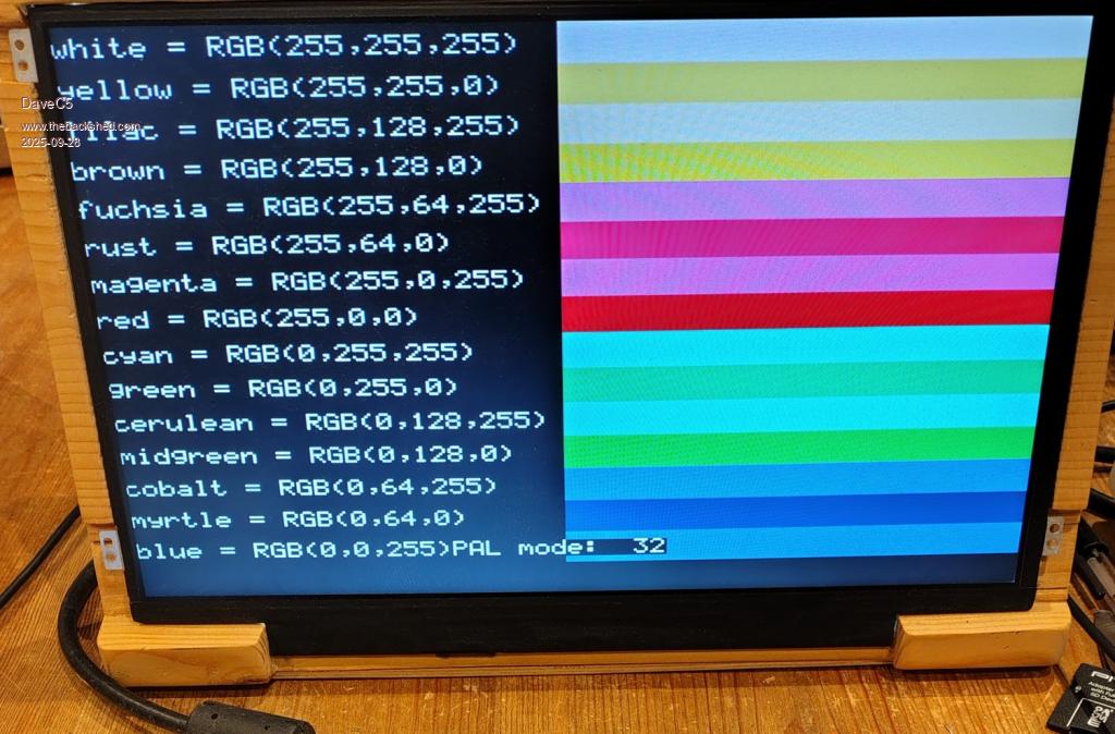 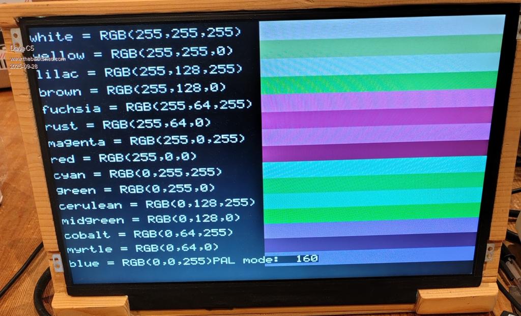 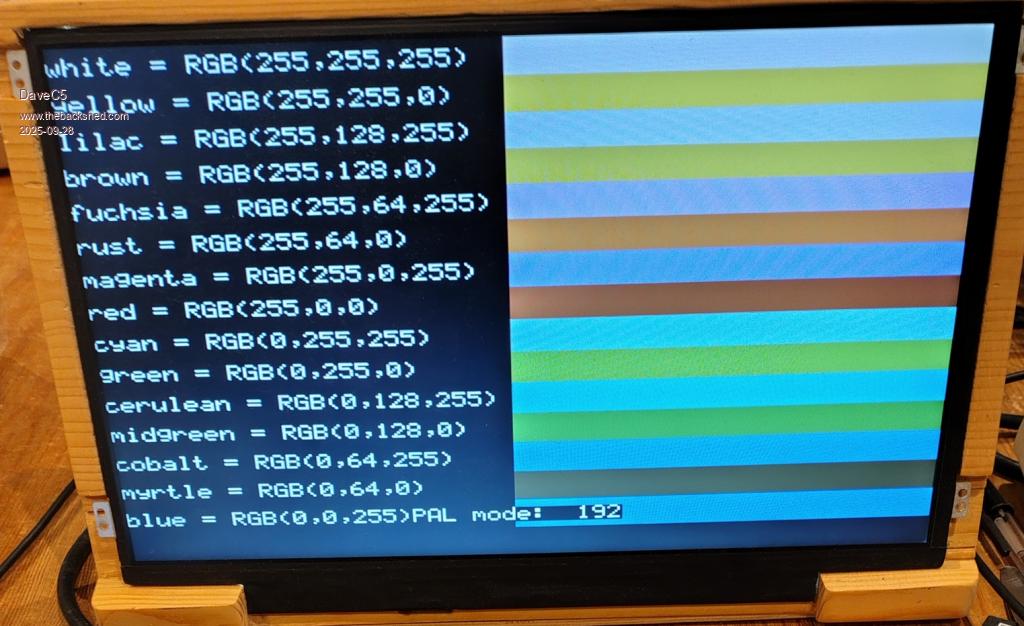 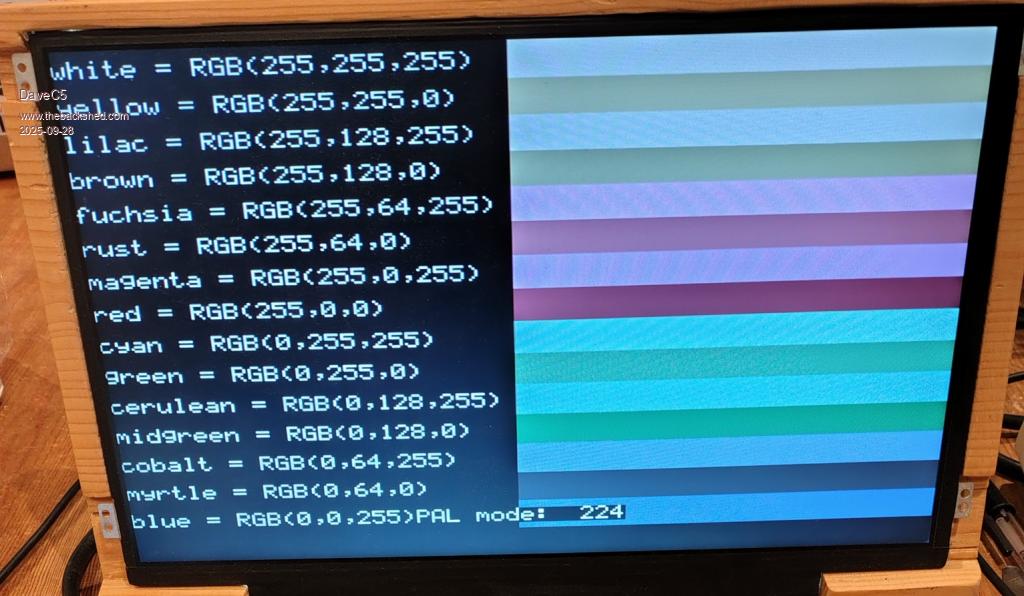 I'll post a breakdown of the connections and what options are available around the power shortly. I'm working on an assembly manual with schematic, notes etc. so will pull the list from that. |
||||
| javavi Guru Joined: 01/10/2023 Location: UkrainePosts: 568 |
Hi Dave, For PicoMite VGA, I consider the most practical palette to be the Windows 16 palette obtained using a simple switch scheme. 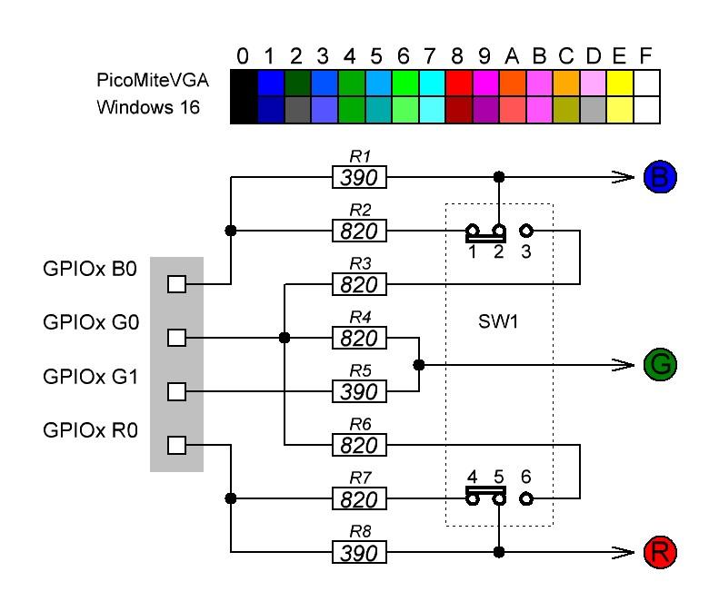 Where can I view your board's schematic for analysis? I might get some helpful ideas and tips.  Edited 2025-09-28 04:48 by javavi |
||||
| dddns Guru Joined: 20/09/2024 Location: GermanyPosts: 874 |
Very nice work! What is your suggestion for PSRAM? Best wishes and success! |
||||
| DaveC5 Newbie Joined: 24/09/2025 Location: United KingdomPosts: 40 |
Hi ddns, Thanks. Unfortunately I don't have a suggestion for PSRAM. I have based the design around the lowest spec devices i.e. the RP2040, which as far as I am aware does not support PSRAM. It will certainly be something I think about adding on a future version, though. Cheers Dave |
||||
| javavi Guru Joined: 01/10/2023 Location: UkrainePosts: 568 |
Hi Dave, 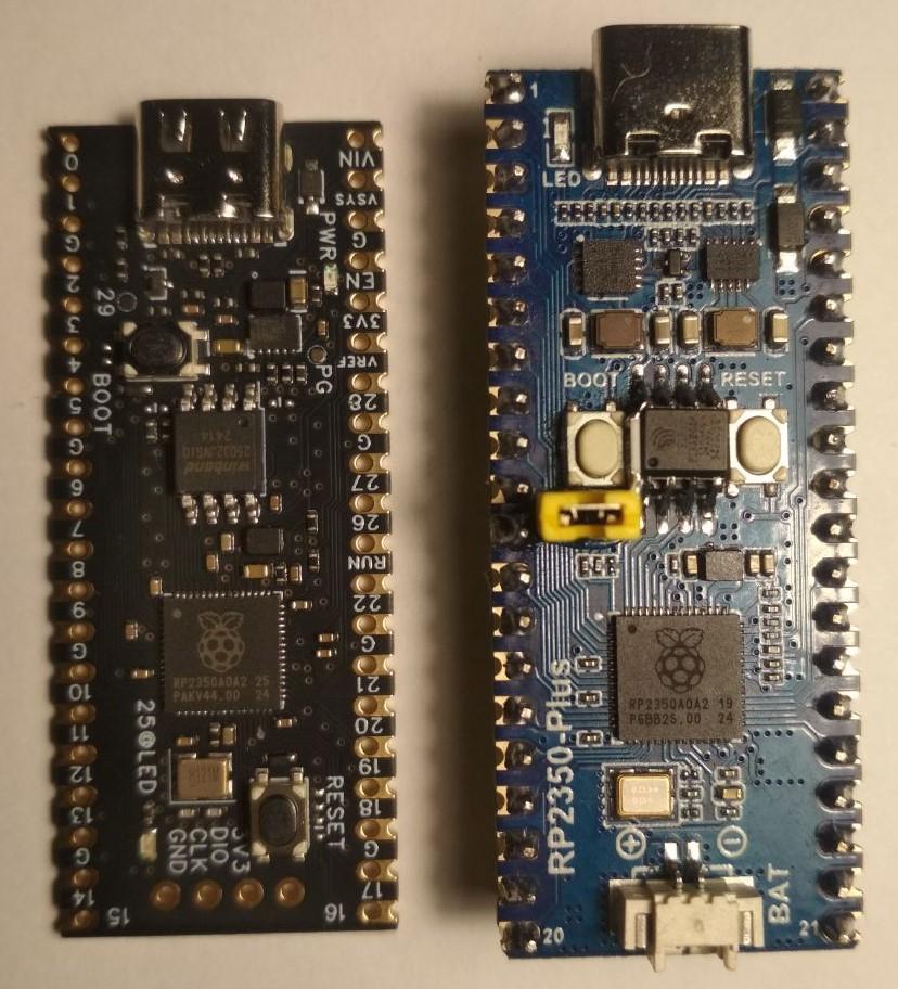 It's fairly easy to solder a PSRAM chip on top of a flash memory chip in a large case on Chinese Pico2 clones. On the right in the photo is a Pico2 clone (RP2350-Plus) with a soldered PSRAM chip and a jumper for disconnecting it from the chip selection pin (CS). Cheers Java |
||||
| DaveC5 Newbie Joined: 24/09/2025 Location: United KingdomPosts: 40 |
Hi javavi, I can't replicate what you've got there exactly, but here's the Palette Shifter. It takes the GREEN channel modifier signal and shifts it around all three channels in all 8 possible combinations, resulting in changes to the non-primary colour parts of the default palette. The challenge was to keep the unique component count as low as possible (all the same resistor value) and it's about the only part of the circuit where a component value is important; the 4066 analogue switch. I've had to go with the specific device that reckons to have the lowest ON resistance. Given the imperfect ON resistance, these are the colour values measured for each of the palettes. The palette number refers to the value sent to U3's output i.e. the upper 3 bits controlling the '4066 switches. 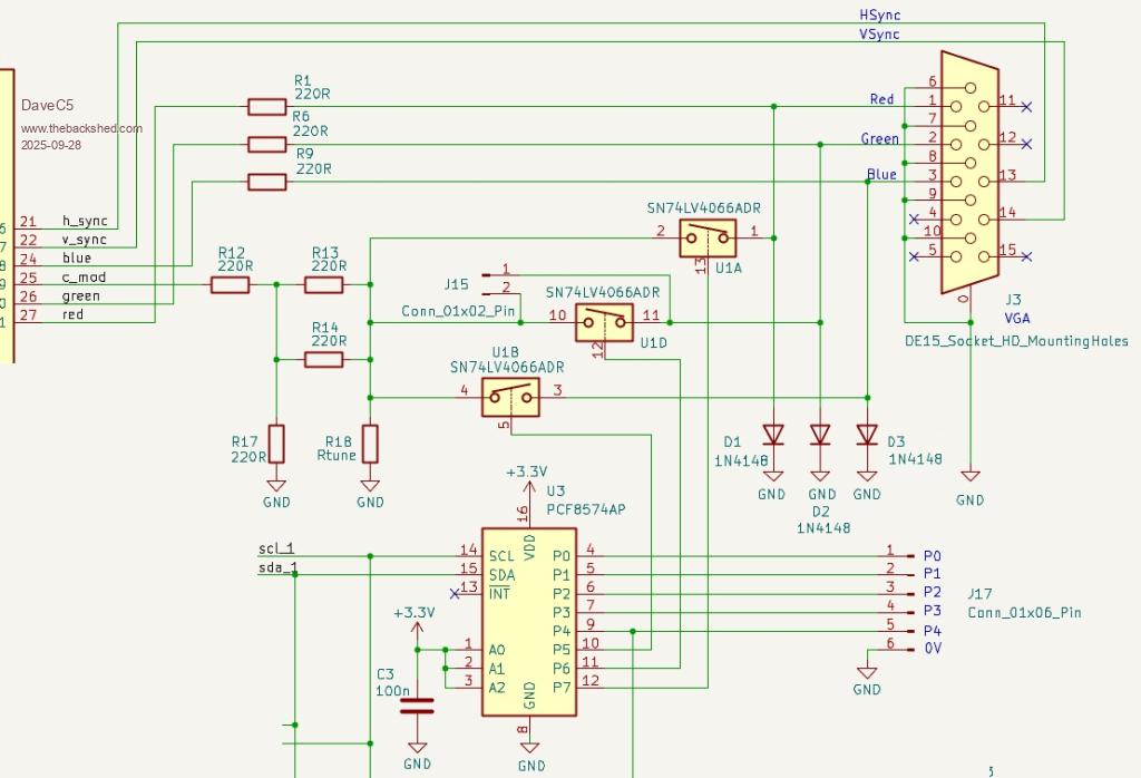 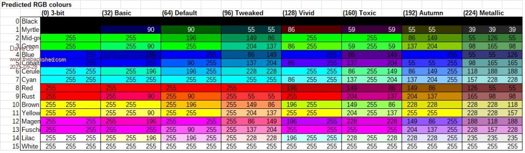 If the Palette Shifter is not wanted, then U1 can be omitted and jumper J15 fitted to make it behave as a standard PicoMite. Cheers Dave |
||||
| javavi Guru Joined: 01/10/2023 Location: UkrainePosts: 568 |
@DaveC5 I looked at your palette switching scheme. It's interesting from a schematic perspective, but I think it's poorly compatible with software and of limited practical use, sorry. My humble opinion is that there's no need to complicate a simple resistor-based VGA scheme; a simple switch will provide an alternative color palette. The exceptional practical advantage of the Windows 16 palette is the two additional shades of gray instead of less commonly used colors. If I had my way, I'd make this palette scheme the default for the PicoMite VGA. It's also worth considering that progress is moving toward an HDMI version of PicoMite, where you can get any color palette. |
||||
| Mixtel90 Guru Joined: 05/10/2019 Location: United KingdomPosts: 8964 |
That's very impressive. :) A nice board with not too much SMD. I like. :) I can't see it, but there may be one omission, a RTC. As a minimum I like to fit a 5-pin male header connector for one of the cheap little self-contained modules, even if it isn't used. If you have I2C on the board already then it costs virtually nothing for the connector, just a bit of board area (and you can arrange it to overlap resistors or the SD card). An RTC is more than useful in that it provides the time and date info for files written to the SD card, making it easier to keep track of program versions. It does have to be on System I2C to be useful in MMBasic though. @Javavi True, the HDMI / USB system is much more powerful but you need the RP2350 too. This is a much more basic board and IMHO is targeted at a different market. It's a bit like comparing a plodding office PC with a gaming machine. They both do what they are needed for. :) Palette switching isn't required at all at this level, it's a "nice to have" and it's way too late to change the VGA standard. That's stuff that HDMI has revolutionized. . Edited 2025-09-28 17:27 by Mixtel90 Mick Zilog Inside! nascom.info for Nascom & Gemini Preliminary MMBasic docs & my PCB designs |
||||
| dddns Guru Joined: 20/09/2024 Location: GermanyPosts: 874 |
I wouldn't do that because the RP2040 might get some future updates but no further development. Otherwise you would restrict yourself in terms of much better specs because of some cent. Your board should run with a standard 2350 and maybe with e.g. this?! |
||||
| Mixtel90 Guru Joined: 05/10/2019 Location: United KingdomPosts: 8964 |
T the moment the end of support date for the original Pico is 1st Jan 2036. I certainly wouldn't design anything that depended on any unofficial module unless I genuinely didn't care if it went out of production in a couple of years. The ideal module to design around now is the Pico 2, which should work fine here even though all the facilities aren't used, after all it's fully pin-compatible and faster. That probably extends the design's life considerably. I wouldn't use any other RP2350 module apart from perhaps Peter's design if I wanted long-term availability. Raspberry Pi don't do one. Cost is an issue too. The Pico is cheaper than the Pico 2 and works. You could take one of these boards and update it with any pin-compatible module, I suppose. This may not be true of a module that has already dedicated GP4 and GP5 to I2C. You have no choice. Mick Zilog Inside! nascom.info for Nascom & Gemini Preliminary MMBasic docs & my PCB designs |
||||
| DaveC5 Newbie Joined: 24/09/2025 Location: United KingdomPosts: 40 |
Hi all, A quick explanation for some of the interesting and valid points raised so far: - you are correct Mixtel90, there is no RTC on board. Frankly I ran out of space for the chip and battery combo and didn't want to have parts on both sides. That said, there is a 4-pin header onboard down near the bottom-right corner that is connected to the 3.3V system I2C bus for just such a purpose. - almost managed to get it all through-hole. There were just a couple of devices that I couldn't get decent options for in THP, not least the micro-SD card socket. - the Palette Shifter is one of those extra quirks I mentioned. Having come across the effect of mis-wiring the signals while building an early prototype build (ahem!) I figured it was at least an interesting thing to allow for, perhaps in a game scenario to toggle background colours, that sort of thing. It has remained only as a way to add a little extra to the most basic versions of the PicoMite VGA. You're absolutely right javavi, the other PicoMite versions don't need it. Also right about the lack of software compatibility with anything (currently) but having fond(?) memories of needing to POKE all sorts into a C64 to get it to do anything it's perhaps not too bad  . All you need to do is write a value to the I2C bus. . All you need to do is write a value to the I2C bus.- there are 2 reasons I targeted the RP2040 boards. Firstly, by designing around the RP2040, the PBC can be upgraded simply by slotting in an RP2350. The other way would not have necessarily have worked. Also, the challenge of keeping the cost to a minimum meant starting with the cheaper device at first, the clone board you indicate is really nice, but it's an extra £10 which I didn't know would be available at the beginning. The main reason, though, is that I happened to have a drawer with 10 RP2040's in it and I wanted to do something with them This isn't a commercial product, it's actually something I'll be giving the kids for Christmas. I say kids, one's a 30-some year old software engineer and the other has just started studying games design, but they've been stricken with the same engineer gene I got, it seems, and I think they both could do with practicing their soldering. Genuinely, thanks for the interest and keep the observations/questions coming. I'll put up the full schematic and parts list shortly so you can take a look. Cheers Dave |
||||
| DaveC5 Newbie Joined: 24/09/2025 Location: United KingdomPosts: 40 |
PicoBuddy Computer Schematic.pdf PicoBuddy Computer v1 parts list.pdf |
||||
| Volhout Guru Joined: 05/03/2018 Location: NetherlandsPosts: 5994 |
Dave, There is a fault in your colour table. U3 cannot switch at the speed of the video pixels. Meaning that it's output is unchanged for the whole video frame. In the metalic palette, U1A, U1B, and U1C are all on. But they are ON during the whole video frame. This results in R, G and B having the same voltage. Your "metalic" palette does not have color, it is 8 levels of grey. Unless you use the internal resistance of the MOS switches (10-52 ohm at 3.3V, typical 35 ohm) in your colour table. But that feels not very reproducible. Similar for other palettes. Please also note that the PCF8574A is not designed to work from 3.3V, the PCA8574 is. I like the way you try to improve the audio, using D16/D18, although C22 might be better placed parallel to R40. Having said that, it is a nice design. Thank you for sharing it. I think it is a very complete. platform that allows for experimentation. The only suggestion I can make is to name the external IO pins the same as the name in MMBasic (gp0 -> gp10, gp4 -> gp22, a0 -> gp26) to make it more logical for junior programmers. Javavi, By re-arranging the 2 jumpers, you can remove 2x 820 ohm resistors. 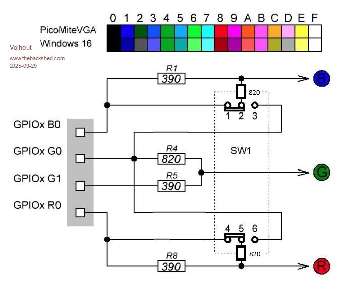 Volhout P.S. about VGA palette: I have looked at putting a re-programmable logic block (minimum a GAL22V10) between the RGB pins and the pico outputs to form a true 64 color option. And re-program it from within the MMBasic program. But most of these small logic chips are OTP (one time programmable) and use much power when speed is needed. And then I realized, no-one would use it except me, HDMI is there. So why bother. Edited 2025-09-29 18:59 by Volhout PicomiteVGA PETSCII ROBOTS |
||||
| Mixtel90 Guru Joined: 05/10/2019 Location: United KingdomPosts: 8964 |
hanks for that little diagram, Volhout. It's helped me simplify the Extended VGA module for my Multi 2 project, moving it from 1206 surface mount to through-hole. :) Mick Zilog Inside! nascom.info for Nascom & Gemini Preliminary MMBasic docs & my PCB designs |
||||
| DaveC5 Newbie Joined: 24/09/2025 Location: United KingdomPosts: 40 |
@Volhout, Hi Thanks for the comments, much appreciated. You are correct, there's no way U3 can switch at pixel or frame speeds, it's really there just routing the C_Mod to change the colours around occasionally. As an example, in the "Blocks" program it could change the colour scheme every time the game speeds up a notch. The values in the table aren't calculations, they are measurements from a couple of the boards I assembled. The only calculation I did was to normalise the results to 8-bits. The "metallic" palette is the fourth one shown in the pictures posted above, and the fact that it has any colour at all is, as you say, the result of imperfect ON resistances in the '4066 switch, which could be quite variable. I'd also wondered about an external digital solution to modifying the palette, but didn't come up with anything satisfactory. I'd thought it might be possible to route the C_Mode signal to R, G and B through individual tri-state buffers and resistors, but couldn't find a suitable device to use The palette shifter doesn't seem to be finding much favour, so I'll probably ditch it in the next version. Maybe replace it with space for an RTC as Mixtel90 suggests. I'm using the PCF8574AN from TI, which reckons to work down to 2.5V https://www.ti.com/lit/ds/symlink/pcf8574a.pdf?ts=1728869550852&ref_url=https%253A%252F%252F The arrangement around D16, D18 etc. is doing a couple of things. The input to R35 is essentially 0-3.3V or thereabouts, but potentially with a lot of PSU noise on it. Using R35 to "drag" the R30 and R40 bias point up and down through the diodes both limits the voltage swing, smooths off some of the rubbish with the forward voltage curve of the diodes, and keeps the signal centred around Vsupply/2. This makes it easier to select an op-amp, as it doesn't need to support rail-rail operation. I've used an MCP6489, but I think most op-amps should work as long as they have a decent bandwidth. C36 forms an R-C filter with R35 to passively attenuate the higher-frequency components of the input signal that can cause issues for Sallen and Key filters when the op-amp phase-shift can't keep up. Good point about the pin naming, I'll be sure to change that. Thanks Dave Edited 2025-09-30 07:43 by DaveC5 |
||||
| Volhout Guru Joined: 05/03/2018 Location: NetherlandsPosts: 5994 |
Dave, If you are thinking about a new board layout, you may want to include below fix 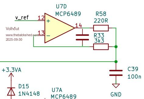 The cap between pin 13 and 14 on the opamp. You need it for stability. The value could be determined by doing a computer simulation, but 1n...10n is typical. Volhout PicomiteVGA PETSCII ROBOTS |
||||
| Page 1 of 3 |
|||||
| The Back Shed's forum code is written, and hosted, in Australia. | © JAQ Software 2026 |
