
|
|
Forum Index : Microcontroller and PC projects : gone build the ref hdmi board
| Author | Message | ||||
| tenij000 Senior Member Joined: 30/05/2025 Location: NetherlandsPosts: 107 |
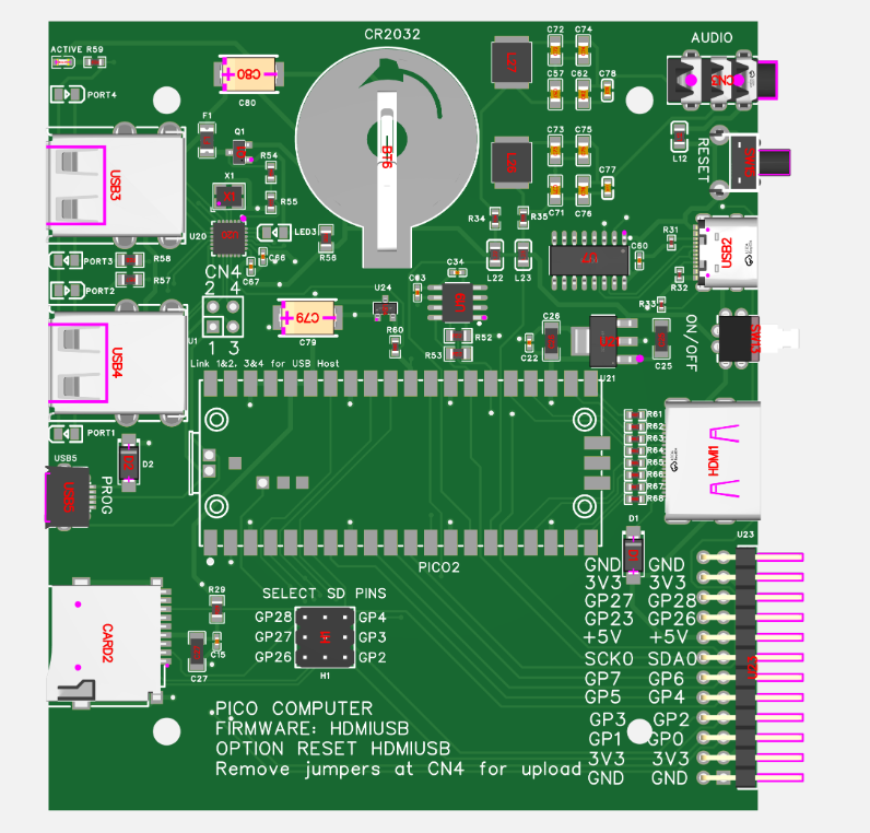 wondering why not made the spot where pico2 goes no holes |
||||
| tenij000 Senior Member Joined: 30/05/2025 Location: NetherlandsPosts: 107 |
those ports1 to port4 are those needid ? just leds ? |
||||
| phil99 Guru Joined: 11/02/2018 Location: AustraliaPosts: 3321 |
The Pico2 is intended to be soldered directly to the PCB. The reason is the USB pads are on the underside of the Pico module. On the PCB the pads that align with them have holes so you can feed solder in to make the join. There should be complete instructions In the "Other Downloads" section here https://geoffg.net/picomitevga.html |
||||
| tenij000 Senior Member Joined: 30/05/2025 Location: NetherlandsPosts: 107 |
can also use pico 2 w on the pcb |
||||
| phil99 Guru Joined: 11/02/2018 Location: AustraliaPosts: 3321 |
No, the WiFi code takes enormous resources. Simply not enough left for HDMI or VGA. |
||||
| The Back Shed's forum code is written, and hosted, in Australia. | © JAQ Software 2026 |
