Home
JAQForum Ver 24.01
Log In or Join  
Active Topics
Local Time 04:08 17 Apr 2026 Privacy Policy
Jump to

Notice. New forum software under development. It's going to miss a few functions and look a bit ugly for a while, but I'm working on it full time now as the old forum was too unstable. Couple days, all good. If you notice any issues, please contact me.

Forum Index : Microcontroller and PC projects : Slab computer

Author Message
DaveC5
Newbie

Joined: 24/09/2025
Location: United Kingdom
Posts: 34
Posted: 05:32pm 28 Feb 2026
Copy link to clipboard 
Print this post

Afternoon all,

I got a bit fed up with working on a bunch of parts spread over the table, so I faffed about with some old MDF drawer-bottoms, a 10" car LCDTV, a Perixx PS2 keyboard and a Pi-Picobuddy board to make something a little more user-friendly.

I really wanted one of those Tandy TRS-80 Model 100's back in the day, and latterly got an Amstrad NC100 and a Sinclair Z88 to play with. The limitation was always the relatively small character display, and the slab format has its flaws, but I still like it for the nostalgic value and now I can pick everything up and carry it around a lot easier.

Cheers
Dave


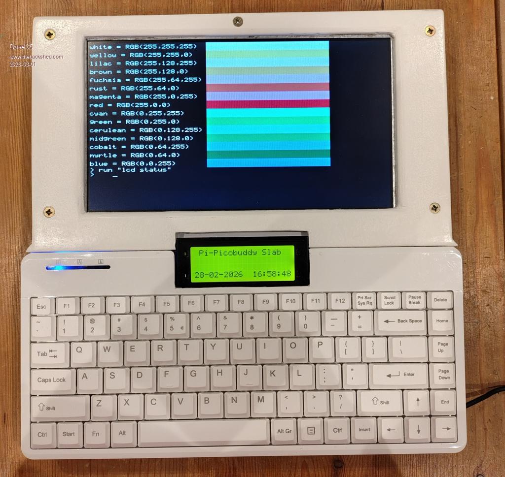
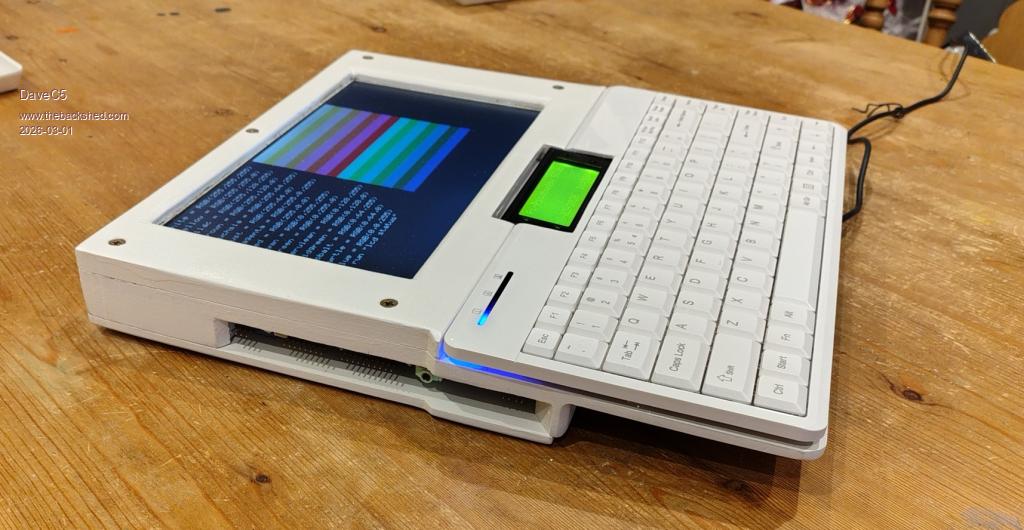
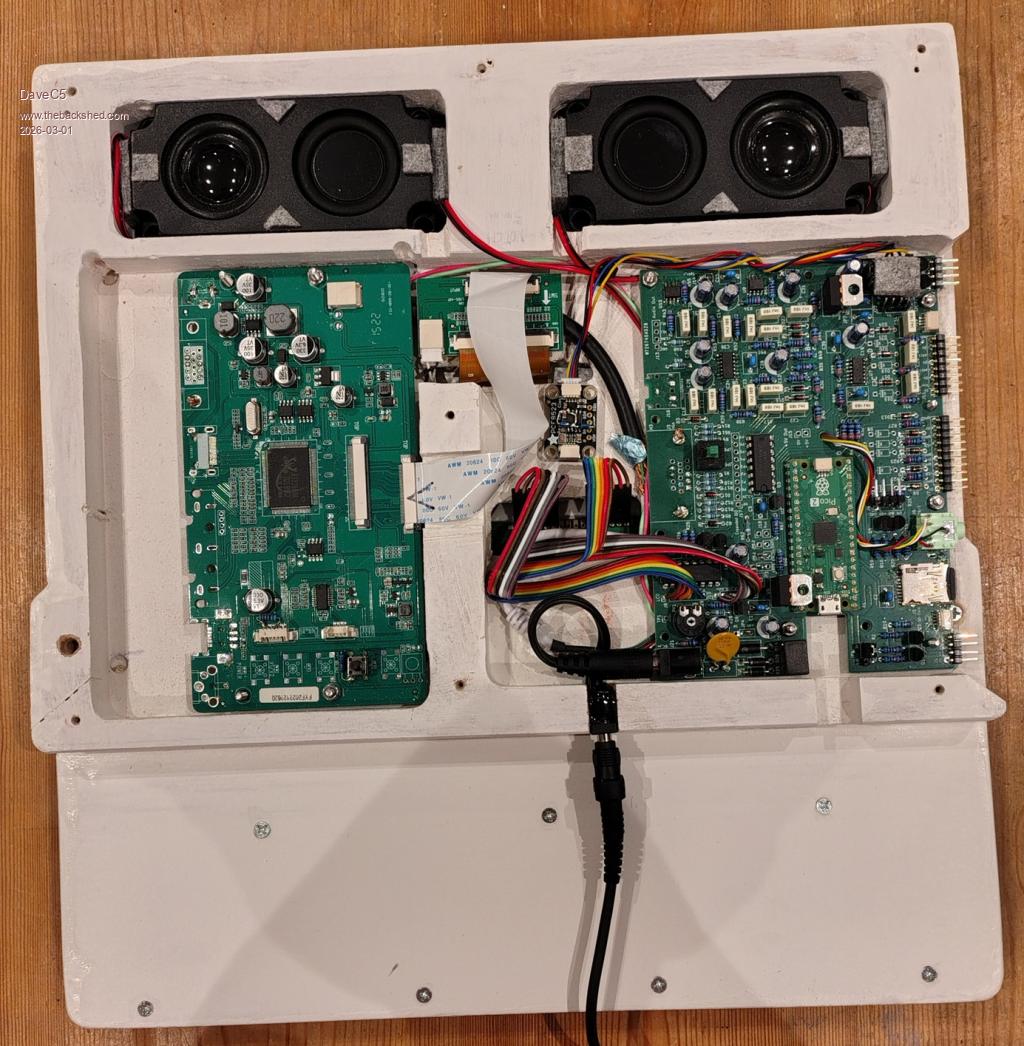
dddns
Guru

Joined: 20/09/2024
Location: Germany
Posts: 819
Posted: 05:42pm 28 Feb 2026
Copy link to clipboard 
Print this post

Super!!!

Edit:
Is this HDMI and what resolution(s) are possible?
Edited 2026-03-01 03:47 by dddns
 
phil99

Guru

Joined: 11/02/2018
Location: Australia
Posts: 3135
Posted: 08:49pm 28 Feb 2026
Copy link to clipboard 
Print this post

In the photo of the internals both the Pi-Picobuddy PCB and the monitor PCB have a VGA socket footprint but I don't see a HDMI one on the Pi-Picobuddy.
https://www.thebackshed.com/forum/ViewTopic.php?TID=18321&PID
Edit.
From pcbway.com
  Quote  PicoBuddy Computer specifications

Based on the Raspberry Pi Pico 2040 microcontoller board running PicoMiteVGA Basic.
Official Raspberry Pi Pico 2350 boards have also been tested and provide greater memory, speed and display modes.
Powered supply options:
+5 V connected to the Pico USB connector
+5 V connected to the 2.1 mm barrel jack (reverse and over-voltage protection).
>5V connected to the 2.1 mm barrel jack (reverse and over-voltage protection) using onboard regulator.
Selection of onboard SMPS or linear regulators to optimise efficiency/noise
2 x I2C busses with STEMMA QT connectors and/or 4-pin headers. Each bus can be independently set to 5 V or 3.3 V operation
PS/2 keyboard input (USB available with the USB-enabled versions of the PicoMite Basic firmware)
Micro--SD card slot
5 x digital I/O
3 x buffered analogue-to-digital inputs, plus buffered 3.0 V reference supply
Stereo PWM output to headphones, or to 8 Ohm speakers via class A/B amplifiers
VGA output, two colour palettes
Onboard HD4487-compatible LCD interface
Onboard 8 x digital I/O

Edited 2026-03-01 07:09 by phil99
 
DaveC5
Newbie

Joined: 24/09/2025
Location: United Kingdom
Posts: 34
Posted: 07:17am 01 Mar 2026
Copy link to clipboard 
Print this post

Hi,

It's just VGA. I have it set to 800x600, which is the native resolution of the LCDTV screen.


  dddns said  Super!!!

Edit:
Is this HDMI and what resolution(s) are possible?
 
DaveC5
Newbie

Joined: 24/09/2025
Location: United Kingdom
Posts: 34
Posted: 07:28am 01 Mar 2026
Copy link to clipboard 
Print this post

Hi,

The LCDTV came with HDMI, VGA, BNC etc. interfaces, and the Pi-PicoBudddy only has a VGA output. To keep everything as compact as possible I removed all the unecessary connectors and hard-wired the necessary pins of the two VGA socket footprints together using a short length of cable salvaged from an old VGA lead, keeping individual screens etc. as intact as possible.

The slightly trickier bit was bodging on a "Source Selection" button so that the screen defaults to the VGA input, since I wasn't using the front-panel board from the LCDTV. It remembers the last setting, thankfully, but I've left the pushbutton as a recessed-access control just in case it ever forgets.


  phil99 said  In the photo of the internals both the Pi-Picobuddy PCB and the monitor PCB have a VGA socket footprint but I don't see a HDMI one on the Pi-Picobuddy.
https://www.thebackshed.com/forum/ViewTopic.php?TID=18321&PID
Edit.
From pcbway.com
  Quote  PicoBuddy Computer specifications

Based on the Raspberry Pi Pico 2040 microcontoller board running PicoMiteVGA Basic.
Official Raspberry Pi Pico 2350 boards have also been tested and provide greater memory, speed and display modes.
Powered supply options:
+5 V connected to the Pico USB connector
+5 V connected to the 2.1 mm barrel jack (reverse and over-voltage protection).
>5V connected to the 2.1 mm barrel jack (reverse and over-voltage protection) using onboard regulator.
Selection of onboard SMPS or linear regulators to optimise efficiency/noise
2 x I2C busses with STEMMA QT connectors and/or 4-pin headers. Each bus can be independently set to 5 V or 3.3 V operation
PS/2 keyboard input (USB available with the USB-enabled versions of the PicoMite Basic firmware)
Micro--SD card slot
5 x digital I/O
3 x buffered analogue-to-digital inputs, plus buffered 3.0 V reference supply
Stereo PWM output to headphones, or to 8 Ohm speakers via class A/B amplifiers
VGA output, two colour palettes
Onboard HD4487-compatible LCD interface
Onboard 8 x digital I/O
 
DaveC5
Newbie

Joined: 24/09/2025
Location: United Kingdom
Posts: 34
Posted: 07:30am 01 Mar 2026
Copy link to clipboard 
Print this post

I should add that it's using the Pi 2 to get 800 x 600

Cheers

  DaveC5 said  Hi,

It's just VGA. I have it set to 800x600, which is the native resolution of the LCDTV screen.


  dddns said  Super!!!

Edit:
Is this HDMI and what resolution(s) are possible?
 
gadgetjack
Senior Member

Joined: 15/07/2016
Location: United States
Posts: 208
Posted: 08:53pm 01 Mar 2026
Copy link to clipboard 
Print this post

Very nice project. Looks great!
 
PeteCotton

Guru

Joined: 13/08/2020
Location: Canada
Posts: 625
Posted: 10:05pm 02 Mar 2026
Copy link to clipboard 
Print this post

Looks great! Thanks for sharing!
 
mozzie
Senior Member

Joined: 15/06/2020
Location: Australia
Posts: 267
Posted: 01:58pm 05 Mar 2026
Copy link to clipboard 
Print this post

G'day Dave,
That is a great looking unit    very nice work.
If you hadn't mentioned it is made of MDF I'd have assumed it was some flashy textured plastic material.

Regards,
Lyle.
 
DaveC5
Newbie

Joined: 24/09/2025
Location: United Kingdom
Posts: 34
Posted: 05:53am 06 Mar 2026
Copy link to clipboard 
Print this post

  mozzie said  G'day Dave,
That is a great looking unit    very nice work.
If you hadn't mentioned it is made of MDF I'd have assumed it was some flashy textured plastic material.

Regards,
Lyle.


Cheers Lyle,

It wasn't great MDF either, the stuff used to make drawer bottoms, except for the thicker slab used to make the housing for the boards which came out of the offcuts bin at the local DIY store.

A couple of coats of Zinnser Bin primer/sealer and some 160 grit-enabled elbow grease worked wonders, though. The Z-B soaks well into the MDF and sets hard, so the surface feels like plastic.

Cheers
Dave
 
Mixtel90

Guru

Joined: 05/10/2019
Location: United Kingdom
Posts: 8760
Posted: 08:43am 06 Mar 2026
Copy link to clipboard 
Print this post

So it's a slab of MDF? Cool! :)
Mick

Zilog Inside! nascom.info for Nascom & Gemini
Preliminary MMBasic docs & my PCB designs
 
Print this page


To reply to this topic, you need to log in.

The Back Shed's forum code is written, and hosted, in Australia.
© JAQ Software 2026