
|
|
Forum Index : Microcontroller and PC projects : DIY RP2350-based Modular Controller for VCV Rack .. in progress
| Author | Message | ||||
| amiga Regular Member Joined: 08/05/2025 Location: BelgiumPosts: 52 |
Hello to all you geeks of good will in these troubled times. A few months ago, I started designing a fully digital Eurorack controller to use VCV Rack as a modular synthesizer. I initially started with a single PCB, but it proved too complex for a non-engineer. I decided to 'divide and conquer' (a tactic favored by some of our leaders), and it’s working beautifully. I designed a backplane PCB that handles all the physical connectivity: potentiometers, jacks, I/O, and encoders. This backplane includes a 5V to 3.3V buck converter, a MAX485 transceiver, and a 40-pin header carrying all signals (32 GPIOs, power, IRQ, and the RS485 bus). It features an RJ45 port to send power and the 485 bus to a 16-port hub powered by a 5V-8A supply. On the processing side, I designed 3 different RP2350-based boards that plug into the backplane: 1 board for pot management (up to 32) 1 board for digital inputs (up to 32) 1 board for jacks with auto-identification (up to 16) The backplane is agnostic, meaning it doesn't care which type of board is plugged into it. All these modules communicate with VCV Rack via a bridge on the laptop/PC. The PCBs are currently at JLCPCB... I’m eagerly awaiting the first signs of life (or the first sparks!). I used EasyEDA and its auto-router, as KiCAD’s learning curve felt a bit too steep for now. @+ alfamiga .. from small country .. but GREAT people .. 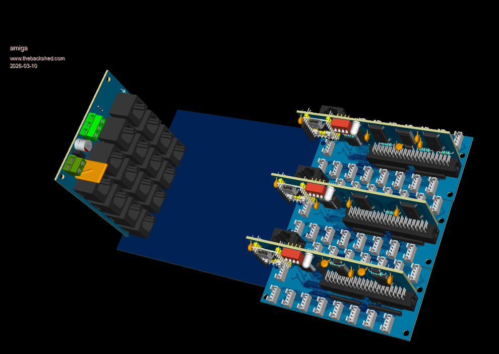 Comments and feedback are more than welcome! |
||||
| lizby Guru Joined: 17/05/2016 Location: United StatesPosts: 3811 |
Very nice. Pico2-Zeros? What do you imagine using the RJ45s for? The 4-pin connectors? How do the boards talk to each other? They look like they're separate, maybe even snapable PCBs. PicoMite, Armmite F4, SensorKits, MMBasic Hardware, Games, etc. on FOTS |
||||
| amiga Regular Member Joined: 08/05/2025 Location: BelgiumPosts: 52 |
I use rp2350-zero from waveshare or clone from aliexpress ... why rs485 ? it's a control for a modular synthetizer working alongside with analog synthetizer .. and a lot of electromagnetic noise !! .. rs485 keep a clean data transmission (i hope) and in the same connector (rj45) i use +5V,GND like a POE and added an IRQ line , usedby all rp2350 to wake up the bridge (in each card there is dip-switch .. assigning a number network from 0-15) . the bridge ask rp2350 with id and ask if there is something for him .. wake-up and poll .. @+ alfamiga |
||||
| lizby Guru Joined: 17/05/2016 Location: United StatesPosts: 3811 |
Sweet. Looking to see more. PicoMite, Armmite F4, SensorKits, MMBasic Hardware, Games, etc. on FOTS |
||||
| amiga Regular Member Joined: 08/05/2025 Location: BelgiumPosts: 52 |
More info : in modular rack synthetizeur ,modules have the same physical control : potentimeters,jacks and digital in/out . Instead making each time a new module (new pcb and sometimes used only one time) . The backplane when connected to a pcb by example : managing potentiometer (32), this potentiometers are available accros the network , and if not enought you can add anothers pcb of potentiometers Several modules having potentiometer can connect their potentiometers to the same backplane or spreaded them across others backplanes . You can mix the pcb gender up 16 in one network of rs485 .. but you can extent the network by adding several other network .. The soft in the bridge (laptop or pc) scann the network and retrieve the network topologie. The bridge create a map with the id of board containing the rp2350 , knows wich type of board (potentiometers,jack,digital input/output) and the id of each gpio assigned to the each pin of the physical connector . The user wiyh a UI , assign potentiometer X to a a gpio Y of a connector Z managed by the bard (rp2350) W . This link is converted in a message to VcV Rack wihch configure the virtual module . When you turn this potentiometer the value is transmisted to VCVrack (using rs485 network) wich change the value of the virtual potentiometer in the virtual module . Same for jacks and digitals IO ... The only things i do is take a plexiglass board fix potentiometers,jack or switch on it ,make a cables and connect them to the backplane .. oouuufti .. no new pcb .. only adapt mapping long typing .. Perhaps confusing , or complex but in fact it's very simple .. like an AppleII @+ alfamiga |
||||
| The Back Shed's forum code is written, and hosted, in Australia. | © JAQ Software 2026 |
