
|
|
Forum Index : Microcontroller and PC projects : complementary PWM outputs
| Author | Message | ||||
| lizby Guru Joined: 17/05/2016 Location: United StatesPosts: 3811 |
I'm building a proof-of-concept H-bridge inverter on a PicoMite RP2350 and need complementary PWM outputs (A high when B low and vice versa) for the high-side and low-side gate drivers. Testing shows that PWM 1, 10000, 50, 50 drives both A and B in phase — not complementary. An overlap test confirmed 45,000+ simultaneous highs out of 100,000 samples, which would be shoot-through in a real H-bridge. My workaround is a 2N3904 inverter on the B output which works fine for the prototype. But I'm curious whether there's a native MMBasic way to get true complementary outputs — perhaps via POKE to the PWM hardware registers, or a CSUB, or something in the PWM command I'm missing? PicoMite, Armmite F4, SensorKits, MMBasic Hardware, Games, etc. on FOTS |
||||
| phil99 Guru Joined: 11/02/2018 Location: AustraliaPosts: 3321 |
There was a couple of years ago. PLAY SOUND had a MONO option that gave complimentary L & R signals for a bridge amplifier. I experimented with this on a small inverter but the 44.1kHz PWM frequency was a bit high for the MOSFETs I was using so switching losses were significantly higher than at 10kHz. Perhaps your PWM could be fed into pin 5 (CT) of a TL494 complimentary PWM driver. It can give a minimum deadtime. Edited 2026-05-18 11:29 by phil99 |
||||
| tom_g Newbie Joined: 21/02/2023 Location: SwitzerlandPosts: 23 |
Hi Phil, manual says " Duty cycles are specified as a percentage and you can use a negative value to invert the output (-100.0 <= duty <=100.0)" Best, Tom |
||||
| AlbertR Senior Member Joined: 29/05/2025 Location: GermanyPosts: 107 |
I think this is exactly the kind of problem PIO (programmable I/O) was designed to solve. It's not exactly “Basic,” but it can be done that way. |
||||
| phil99 Guru Joined: 11/02/2018 Location: AustraliaPosts: 3321 |
Thanks Tom, I had forgot about that. Lizby will still need incorporate deadtime components between the Pico outputs and the MOSFET drivers to prevent "shoot-through". MOSFETs take longer to switch off than to switch on so the switch-on needs to be delayed to compensate. Yes PIO could provide complimentary outputs with deadtime but my tired old brain is past that now. Edited 2026-05-18 16:18 by phil99 |
||||
| tom_g Newbie Joined: 21/02/2023 Location: SwitzerlandPosts: 23 |
Phil, you can apply phase-correct mode in order to center both slices, use complementary and unequal duty amounts to produce precise deadband behaviour. Be aware that PWM period is halved when applying phase-correct mode. Details can be found in RP2040 datasheet from P.546 on. ( You can always POKE into the registers, if any need: ex. POKE WORD &H40050000,7 ' reconfig PWM slice 0 to run with phase correct mode, invert PWM0A and enable ) Best, Tom |
||||
| matherp Guru Joined: 11/12/2012 Location: United KingdomPosts: 11636 |
This should all be doable with the inverted output and synch capabilities of the PicoMite. Synch is the key allowing two separate PWMs to be linked with an offset so that deadtime can be achieved as required |
||||
| Volhout Guru Joined: 05/03/2018 Location: NetherlandsPosts: 5994 |
@lizby, If you need exactly inverted outputs, from a single PWM, you can use negative PWM values. Note that the PWM value is a float, so you can get resolution that is built in the PWM hardware. Pico peripherals work at 60-ish MHz (63 or 66). So when you run a 60kHz PWM you can get 10 bit resolution (2^10 = 1024). When you run 15kHz it will be 12 bit. The PWM's have 2 outputs A and B. PWM n,freq,duty,-duty will get you what you want. A has "duty" as dutycycle, B has "100%-duty" as dutycycle. The dead time has to be made in hardware. But to drive an H bridge, you often need 2 PWM controlled pulses with 180 degrees phase difference. Then you can use 2 different PWM, that you phase lock. Then use output A from PWM1 and output A from PWM2 to drive the H bridge. You need to use PWM SYNC to start the 2 PWM's simultaneous. Now you can have A a duty cycle of 20%, and B also with duty cycle 20%, but they are 180 degrees appart. The dead time is now also easy to implement: have a maximum duty cycle of 49% (not 50%). IF you look at example 3 in the user manual appendix F (this appendix is about PIO) it shows in a few lines (Phill's idea) how to create 6 H bridge signals for a 3 phase H bridge from 3 independent PWM's that are phase locked. Note, this is 50Hz, and they are 120 degrees appart. 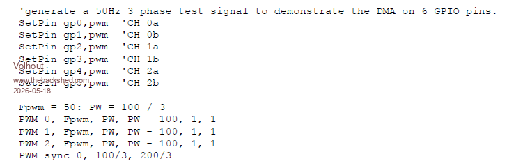 In this example it is used to demo a simple logic analyzer running on PIO. But the test signal can be used to do what you need. Volhout Edited 2026-05-18 16:49 by Volhout PicomiteVGA PETSCII ROBOTS |
||||
| tom_g Newbie Joined: 21/02/2023 Location: SwitzerlandPosts: 23 |
to be clear, phase-correct mode is specifyable within PWM channel, frequency,[dutyA][,dutyB][,phase][,defer] (as described in manual) ex. PWM 0, 50000, dutyA, -dutyB, 1, 0 Tom |
||||
| The Back Shed's forum code is written, and hosted, in Australia. | © JAQ Software 2026 |
