Notice. New forum software under development. It's going to miss a few functions and look a bit ugly for a while, but I'm working on it full time now as the old forum was too unstable. Couple days, all good. If you notice any issues, please contact me.
Mixtel90 Guru Joined: 05/10/2019 Location: United KingdomPosts: 9171
Posted: 09:15pm 07 Jul 2026
Copy link to clipboard
Print this post
I started this design prior to going out of commission for various reasons (including a stay in hospital). I dug it out again the other day to see if my brain was up to working again (epilepsy leaves me a bit off, sometimes for weeks). Things seem to be ok, even if I'm still suffering from some of the physical problems!
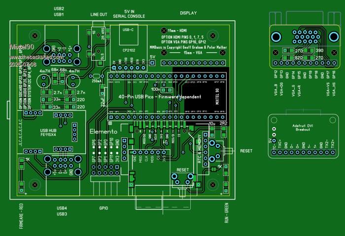
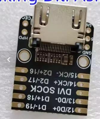
So, Elemento. The enclosure costs about £1.47 from AE. No screws, just clips together. AE link The PCB is my first serious attempt at a 4-layer board. Designed to be easy to assemble for just about anyone who can solder. Although there is SMD work there is nothing smaller than 1206. The bits you *will* break while practicing are the two LEDs. lol Built in 4-port USB hub Will accept either the Adafruit DVI breakout module for HDMI or a little board for VGA output. Choice of 2 different full size SD card sockets or a micro SD card module (not SMD). RTC with CR2032 40-pin Pico socket.
You need a short lead with a "mini" plug to fit your Pico and D+ / D- connecting to the hub. You simply unplug it for installing MMBasic then reconnect it.
Eight uncommitted GPIO pins on the front for the user. PWM audio. Sorry, but there's not much space and I can't hear stereo anyway!
The clever bits are the changeable display module and the Pico. The 40-pin layout is completely standard so any pin-compatible device can be used. You will probably want to run the USB firmware though as otherwise your only access is the console. In theory it will accept anything from the original Pico to the Pimoroni Picp Plus 2 W and you can upgrade from one to the other. The VGA module is the same footprint as the Adafruit module. Both are intended to be screwed down onto M2.5 tapped spacers to reduce the strain on the connections. Note that you have to fit the display board *after* screwing the PCB down as there is no access to this screw after.
As usual with my designs, the components are generally cheap and cheerful. I'm just starting to check it over so comments welcome.Mick
Mixtel90 Guru Joined: 05/10/2019 Location: United KingdomPosts: 9171
Posted: 08:14am 08 Jul 2026
Copy link to clipboard
Print this post
For that simply plug in the Pimoroni Plus 2 W. :) Linky It's not a cheap module (£16.80) but it includes 16MB flash, 8MB PSRAM and Qwiic. I think the PSRAM select is on GP47, where you would expect it for Pimoroni. It may be changeable, I'm not sure.
If you aren't bothered about wifi/bluetooth then they also do the pico-plus-2 for £12.90 in the same form factor. You may get the A2 stepping chip though.
I don't know of any other 40-pin module that includes PSRAM.
I'm guessing that the cases were intended for something like an active antenna. The outer finish is far nicer than I'd expect for something like a thermostat and the cable entry position is nicely rounded (I tried but I couldn't make use of it!). . Edited 2026-07-08 18:17 by Mixtel90Mick
Volhout Guru Joined: 05/03/2018 Location: NetherlandsPosts: 6158
Posted: 06:47am 09 Jul 2026
Copy link to clipboard
Print this post
Mick,
Maybe a stupid question, ... why not put the VGA down on the main board. For HDMI, simply do not populate the parts, and stick the adafruit board in.
I checked the housing, and you have to put the board in sideways (the cooling ribs are at the side). How can you put the board in when all holes for the USB/VGA/audio/reset switch stick out on both sides (front/back of the PCB, but sides of the gutter form top of the housing ?
Mixtel90 Guru Joined: 05/10/2019 Location: United KingdomPosts: 9171
Posted: 07:52am 09 Jul 2026
Copy link to clipboard
Print this post
I did consider doing that with the VGA but there is a problem with the PCB fixing screw in that corner. There is no access to it so to get the display connector as tight into the corner as possible it has to plug in. So both the VGA and the Adafruit module are mounted connector-side down, on spacers.
Nothing along the front or the sides of the board projects through the front or sides of the case. Or at least it shouldn't. :) Reset buttons are supposed to be "down a hole and poke it with a stick" type. It should be easy enough to hook the rear components of the PCB into the case then hinge them together.Mick
Mixtel90 Guru Joined: 05/10/2019 Location: United KingdomPosts: 9171
Posted: 08:51am 12 Jul 2026
Copy link to clipboard
Print this post
Right, I have a set of slightly modified prototype boards on order. That includes a veritable host (5 panels of 8 each) of the VGA adapter modules. :)
I don't know if anyone can use a module that allows a VGA monitor to be connected to the HSTX pins as laid out for the Adafruit DVI breakout. It could also be used a combined socket and resistor matrix to plug into a breadboard. No promises yet, but I'll see what they are like when they turn up. It's my first attempt at using JLCPCB's panelizing system with V cuts.
The main boards are, as I mentioned previously, my first serious attempt at working with 4 layers. It's passed my usual SL6 point-to point checks and the DRC so most of it might work. :)
The total cost of all the boards, including standard "el cheapo" shipping and taxes, was £18.95.
No gerbers yet. I'd rather like it to work first. :) The circuit diagram is almost done and I'm fairly well on with the manual. Yes, I still do manuals. :)
Still need to get some more bits from AE - I'm running out.Mick
Ok, so the SD card on the display isn't used and there's no brightness control but the LCD display is fitting onto the same HSTX pins ising a simple adapter over shortish wires. :)
Internally the SD card is on SPI2, but on different pins. Just redefine it for bitbang mode.
Mixtel90 Guru Joined: 05/10/2019 Location: United KingdomPosts: 9171
Posted: 07:53pm 12 Jul 2026
Copy link to clipboard
Print this post
That's fine. My board has a 5V header and the Adafruit board is fitted with a flying lead to plug into it. A LCD board could work in the same way. If you want 3V3 for the display then that could be fed from that, I suppose. I had to do it that way as the VGA connector would hit a 5V header aligned with the Adafruit.
Remember, the display boards are "upside down" so that they can be lifted high enough to miss the PCB fixing screw and still fit into the case. :)Mick
Mixtel90 Guru Joined: 05/10/2019 Location: United KingdomPosts: 9171
Posted: 03:00pm 14 Jul 2026
Copy link to clipboard
Print this post
I'm just toying with ideas for the next revision. I've come uo with these:
An option to plug in a ribbon, probably on a 2x6 box header, for a LCD display. A module similar to the VGA one but different connector and using the same fixings. If the display wants 3V3 then it will have to come from the board's 5V anyway. I don't want the display load going on the Pico's regulator.
Flip the RTC over so that the existing pins can merely be straightened and a 4-pin header put on the other end. I think I drew it like this originally but flipped it to put the battery on the bottom for some reason. Probably ancient brain fade - think of it as correcting a stupid error ... :)
Add the option of a second identical GPIO port next to the existing one. This would remove the option of a SD card though, so it would replace it by adding GP22 to the LCD connection by introducing an additional socket between H2 and H3. Of course, there would be no SD card available on VGA or HDMI versions. I'm not terribly happy but it does get access to the ADC inputs. Of course a micro SDcard socket module is available that could do it anyway and that may be the answer.
pwillard Guru Joined: 07/06/2022 Location: United StatesPosts: 347
Posted: 08:02pm 19 Jul 2026
Copy link to clipboard
Print this post
It's weird that the AliExpress Box has built-in standoffs, but they are not all the same height.
Mixtel90 Guru Joined: 05/10/2019 Location: United KingdomPosts: 9171
Posted: 09:13pm 19 Jul 2026
Copy link to clipboard
Print this post
I suppose it didn't matter for the intended purpose. :)
I have prototype boards on the way so it'll be playtime soon. The AE case will probably work ok with a bit of careful surgery. I have a couple more on order to practice on. At least I found my bag of #4x6mm screws. :)Mick
pwillard Guru Joined: 07/06/2022 Location: United StatesPosts: 347
Posted: 12:22am 20 Jul 2026
Copy link to clipboard
Print this post
Yeah, 3 of them are around 3.3 mm, and one is 5mm tall. Weird.
phil99 Guru Joined: 11/02/2018 Location: AustraliaPosts: 3401
Posted: 12:28am 20 Jul 2026
Copy link to clipboard
Print this post
The difference is about the thickness of a PCB, ~1.7mm. You could make 3 PCB washers to sit on the others instead of grinding the high one down.
Mixtel90 Guru Joined: 05/10/2019 Location: United KingdomPosts: 9171
Posted: 07:10am 20 Jul 2026
Copy link to clipboard
Print this post
If I measure the total thickness, including that of the base, then only one support is lower than 5mm - and that's barely lower. On examining the highest support it's pretty clear that the additional height is the result of poor separation from the mould (it's dished) - the interior finish is a bit rough in general. The remaining two appear to have no particular reason for being what they are.
Until my next examples appear I have no idea if the inconsistencies are the same.
Addendum: Unfortunately I have neither the brain to design nor the equipment to produce a 3D printed alternative - but if others wish to do so they are quite welcome to. My only real alternative was the RM2014S which is a great little case but not terribly easy to find from suppliers that don't have high postage charges. Most suppliers of that range only carry the M and L versions.
Mixtel90 Guru Joined: 05/10/2019 Location: United KingdomPosts: 9171
Posted: 11:02am 24 Jul 2026
Copy link to clipboard
Print this post
The extra enclosures appeared this morning (along with the PCBs) so I checked them for fit. The inconsistencies seem to be about the same, although I didn't measure anything.
I leveled up the standoffs by putting three M5 plane washers over them then just shaving the top off with a sharp knife. The plastic is soft so sandpaper will work.
I need to rethink the PCB fixings and allow more play. A clip-together case is very unforgiving and tightening the board fixing screws will easily warp the base to the point where the clips don't work - and that's not far at all. Double checking the *actual* standoff positions and increasing the hole diameters should sort it out, I think.Mick
Mixtel90 Guru Joined: 05/10/2019 Location: United KingdomPosts: 9171
Posted: 03:18pm 25 Jul 2026
Copy link to clipboard
Print this post
Oh dear..... Looks like my first real attempt at 4 layers hasn't worked. There are problems on the new boards that aren't on the design that I did. It's probably something I did wrong somewhere along the way. In the meantime, temporary end of project. :(Mick
Mixtel90 Guru Joined: 05/10/2019 Location: United KingdomPosts: 9171
Posted: 07:07am 26 Jul 2026
Copy link to clipboard
Print this post
A bit early to give up. :) Yesterday evening I had another look at the board, made another copy of the file and switched off the internal layers. Then looked at what I could do with what was left. I *think* I've managed to convert it to double-sided without moving any major components. I'm just about at the testing stage now.
The fixing holes now work without deforming the base of the enclosure, simply by opening them up to 3.2mm, which is a more sensible clearance for a #4 screw in a TPH hole anyway.Mick

 Notice. New forum software under development. It's going to miss a few functions and look a bit ugly for a while, but I'm working on it full time now as the old forum was too unstable. Couple days, all good. If you notice any issues, please contact me.


 Print this post