
|
|
Forum Index : Windmills : Project update
| Author | Message | ||||
CanTinker2 Newbie Joined: 21/01/2008 Location: CanadaPosts: 14 |
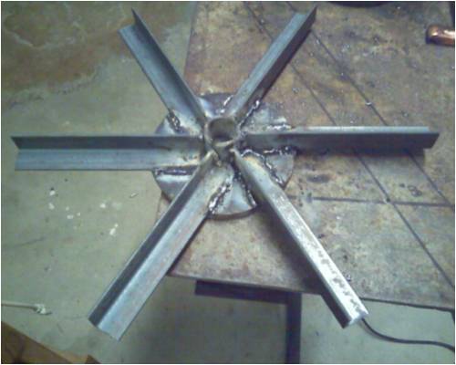
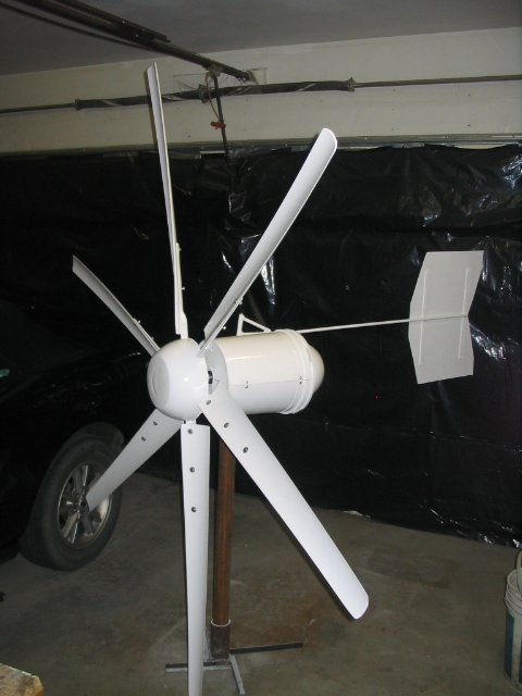
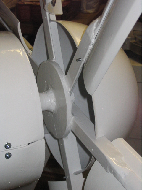
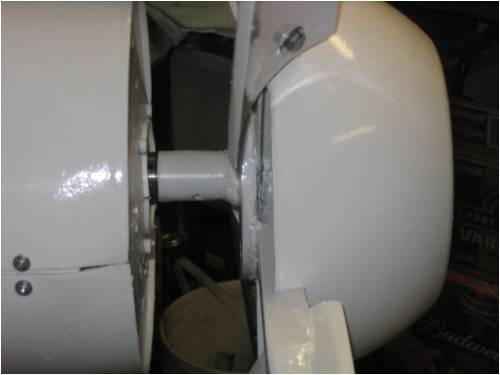
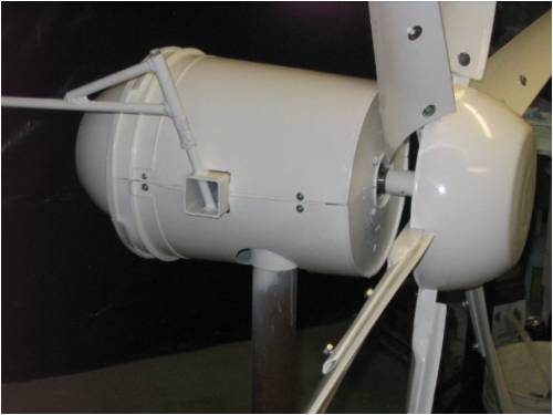
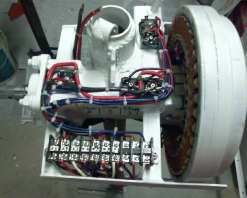
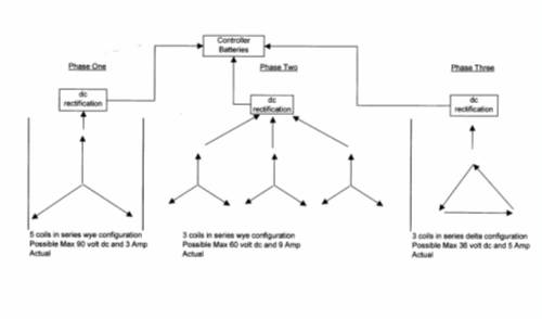
Hey Guys For my winter project, I've been working on my windmill when I get the time and it's coming along quite well. Typically windmills have 3 blades to achieve a higher RPM. I followed Glenn's idea for 6 blades, mine are about 7 feet in diameter. The 6 blades are to catch more wind for more torque while the blades still are angled as if there were 3. Hopefully this should still achieve high RPM for high output in higher wind conditions. I found the calculations for blade angle confusing and somewhat different from one article to another however I ended up choosing 9 degrees from the plane of rotation which I suspect should be a TSR of around 4. To match the input I've again used Glenn's stator design, to have a lower maximum output in favor of some power output in lower wind conditions, so the average monthly output should be significantly higher than the original plan. To do this the generator is wired into 3 separate generators with different voltage outputs so that the harder the wind blows the harder the generator works. I revised Glenn's design for one stator to have 3 stages. The first stage will cut in early by attempting to generate a max of around 90 volts by using 5 coils in series in a wye configuration. The second stage cuts-in in slightly higher winds with a max of 60 volts, 3 coils in series in a wye configuration. The third will only cut-in in high winds with a max of 38 volts consisting of 3 coils in series in a delta configuration. The second and third stage can be rewired on the terminal block from a wye to a delta configuration for flexability depending on actual results, this may also help if I decided to connect it to a 24 volt system in the future. The blades were cut from a 8 inch PVC pipe again following Glenn's 6 blade design. Although if I make another set I would sand off the inside instead of the outside of the pipe on the trailing edge of the blade. I suspect this would make a more suitable airofoil. The hub is round plate steel with 6-1 inch angle iron blade supports welded. I welded a 1 pipe to the back of the hub to slide over the P&P shaft and drilled a hole through the pipe and shaft for a 1/4 inch bolt. I hope this simple design works well and I will be able to remove the hub if needed. The tail is 1/2 rod, 1.2 meters long. The vane is the tin from an old diswasher front. It is a little thin, I hope it works. This part of the windmill project is now complete and I am anxious to test it. The next stage is the tower, my design is for a 35 foot tower with a folding mast. This project is now on the back burner but it could be flying by the long weekend. I have started to think about the controller. I am considering a simple voltage circuit with an automotive relay for the switching simular to the newer controller now posted. My dump load will be an old convection electric 2 KW heater. More somber news, My wife has been diagnosed with a brain tumor. We are looking on the bright side; it is not cancer, has been discovered before its too large (1 inch) and Winnipeg has the 2 best brain surgeons / equipment in Canada. Like I said we are attempting to remain positive, not dwell on the situation and continue to live life for all its worth. Thanks for all the help in this exciting project. I have attached several pictures of the progress and yes the generator cover is a 5 gallon pail, the rotor cone a salad bowl. Later John 08_2023.jpg"> 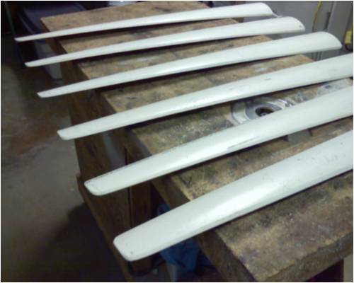
|
||||
| wind-pirate Senior Member Joined: 01/02/2007 Location: CanadaPosts: 101 |
Hi John 6 Blades... "Interesting" You will have more power in low winds, But will the speed be there. Mixing bowls, 20 liter pails. Thats recycling. Good work. Keep us posted with the results. Sorry to hear of your bad news. We wish you well and speedy recovery from Saskatchewan. The pirate Ron THE Pirate. stealing wind & solar energy is fun |
||||
| GWatPE Senior Member Joined: 01/09/2006 Location: AustraliaPosts: 2127 |
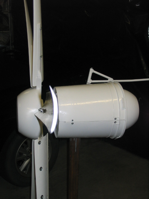
Hi John, sorry to hear of your bad news. I hope things have a good outcome. I do notice you have mentioned a 1/4" bolt to hold the rotor and drilling the shaft. The pic above, that you provided shows what you have done. The shaft is now significantly weaker and the rotor mass is on the outside as well. If the whole rotor was flipped, so the hole was now on the outer edge, this would be a stronger setup. I hope you can see what I mean. .. .. Gordon. Edit: Any time a hole is drilled in a shaft, the weakening of it should be considered. There are considerable stresses at that point and it would be probable that the whole rotor would eventually snap off at the bolt hole, with the broken stub end still in the rotor. I did not mean to reverse the rotor, but place the bolt hole on the other side of the rotor disk. This shaft may still be used if there is enough length to alllow the use of the original hole, but with much more of the tube and rotor, closer to the bearing along the shaft. The amount of work done by the mill and rotor balance will determine the service life. You will need to determine if there would be any risk if the shaft was to snap as a result of a weakness that you caused. Upon looking at the pic again, I would scrap the shaft. become more energy aware |
||||
Gill Senior Member Joined: 11/11/2006 Location: AustraliaPosts: 669 |
G'day John, Thanks for the project update. It certainly looks ready to tackle some serious battery charging. 
I'm ignorant of the 'WYE' configuration. Is that the same as 'STAR', if not, what is it's arrangement please? On the personal side, your positive attitude and support together with the best medical team available and you're set for the best outcome. 
And if Best Wishes count, you have mine.  was working fine... til the smoke got out. Cheers Gill _Cairns, FNQ |
||||
| Tinker Guru Joined: 07/11/2007 Location: AustraliaPosts: 1904 |
Gill, 3 phase circuits are also known as wye/delta. This comes from the resemblance to the letter Y. Tinker Klaus |
||||
| Gizmo Admin Group Joined: 05/06/2004 Location: AustraliaPosts: 5182 |
Hi John Thats a nice looking machine, very well made. I cant wait to see how the blades and staggered stator work for you. My own stagered stator and 6 blade turbine just works, there is nothing I want to change on it. On the weekend I was in the workshop and saw the mill make over 200 watts several times. Its not the most powerfull windmill I've had ( the best so far was a 7 phase with Trev's new fibreglass blades at 330 watts ) buts its always making some power, even if ony a few watts. I think you will be happy with it. Hope all goes well for the other half. Keep us posted. Glenn The best time to plant a tree was twenty years ago, the second best time is right now. JAQ |
||||
| KiwiJohn Guru Joined: 01/12/2005 Location: New ZealandPosts: 691 |
Hi John, Nice work! Sorry to hear of your wife's condition, good treatment and your great attitude are the best combination to get you through this sort of thing. We have had some experience of cancer here (my sister and I), one of us was looking pretty grim and the other not so bad and now we are both out the other side, I used to tell myself "Life is an adventure and all good adventures have some hard bits along the way". Best wishes to you both . |
||||
| CanTinker2 Newbie Joined: 21/01/2008 Location: CanadaPosts: 14 |
Thank you all for your kind feedback. Does any one have a good understanding (based on experience) of the TSR relationship to the plane of rotation? With all of my research I found the documents and explainations simular, however the final outcome of the calculations would come out to a different blade angle compared to the plane of rotation. The way I see it, this is the only physical measurement that I can make in advance. I always used the angle of attack of 5 degrees and used the table found on this site which for 3 blades, results in a blade angle of 8.5 degrees. I have a great respect for the experience and expertice on this site and I noticed that Glenn used a 5 degree angle of attack for his 6 blade generator. Thanks again John |
||||
| Gill Senior Member Joined: 11/11/2006 Location: AustraliaPosts: 669 |
G'day John, I am having some difficulty understanding what you are referring to as the term 'plane of rotation' to me means the prop is rotating in the vertical plane, perpendicular to the actual wind, and in your question this does not make sense to me. Further, I cannot see what it is you may be referring to. Are you concerned that your blade angle of 8.5 is not the same as Glenn's 5? If as you say you research and the documents with their explanations have not clearly shown the relationships, it is difficult to know what to help with. It is more of an art or craft for the DIY windmill maker to select TSR, blade material, profiles, diameters and angles of attack, etc than it is a science with established formulae for every possible combination. There is therefor no fixed or correct procedure for verifying the specifications one builder uses compared to say another. Nor is there any set way for you to arrive at 'guaranteed' 100% max efficiency, perfect set of say PVC blades. The best you can hope for is to understand (as much as is possible) the relationships and effect different parameters will have and make an educated GUESS (as best as you are able) to arrive at a compromise for the conditions of intended use. So there's my ramblings on a question I did not understand. Do you have more specifics?  was working fine... til the smoke got out. Cheers Gill _Cairns, FNQ |
||||
| petanque don Senior Member Joined: 02/08/2006 Location: AustraliaPosts: 212 |
Looks like a nicely made machine. From my experience plastic buckets are not that well UV stabilised and are likely to deteriorate within 12 months. I may be something to monitor. |
||||
| KiwiJohn Guru Joined: 01/12/2005 Location: New ZealandPosts: 691 |
I have a plastic bucket covering the top of an unused chimney and it has been up there in the sunlight for about 10 years. What I did was covered it with an old cotton sheet well soaked in house paint!  |
||||
| GWatPE Senior Member Joined: 01/09/2006 Location: AustraliaPosts: 2127 |
Hi CanTinker2, I think KiwiJohn recommends a coat of house paint, probably acrylic paint and white in colour. The white pigment has good UV stability. I would not bother with the cotton sheet... .. Gordon. become more energy aware |
||||
| KiwiJohn Guru Joined: 01/12/2005 Location: New ZealandPosts: 691 |
My theory is that the house paint does not stick to the plastic bucket very well but by using the cotton I can build up a really thick coating. I first rip the cotton into small strips and dampen them a little in water, slop some paint on the object, add a piece of cotton to the wet paint then give it a good layer of paint on top, multiple layers of cotton are even better. This is a variation of an old technique for sealing the decks of wooden boats. I have done it on a few things even a 'temporary' MDF letter box that lasted 15 years and then only fell apart because the rubbish truck hit it. |
||||
| CanTinker2 Newbie Joined: 21/01/2008 Location: CanadaPosts: 14 |
Hi Gill By plane of rotation I was refering to the angle of blade in comparison to the direction of blade travel. 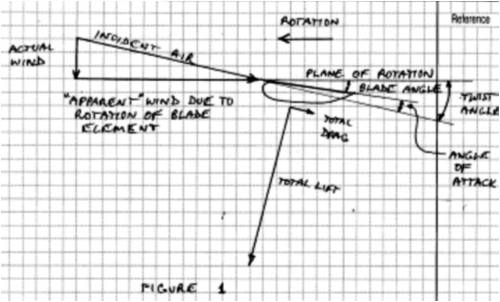
I know what you mean about paint and plastic. To protect the plastic from UV, I sanded the PVC blades, the plastic bowl (rotor cone) and 20 liter bucket (generator cover) with 120 grit sand paper then painted with 5 coats of Tremclad white outdoor rust paint. Usually sanding the plastic gives the paint something to stick to. John |
||||
| Gill Senior Member Joined: 11/11/2006 Location: AustraliaPosts: 669 |
John, The Tip Speed Ratio is the ratio of tip speed to wind speed per revolution. The Bight of Air(my term) per rev and the prop circumference(one rev) reflect this ratio. It also gives the blade angles(feathered) to which we must apply an Angle of Attack for a driving force. Note: this ratio theoretically applies over a large range of wind velocities provided generator loading does not exceed available wind power otherwise we approach stall where TSR drops and Angle of Attack increases. 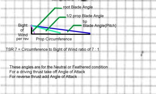
A query appeared on an OtherForum relating to prop lift as you have drawn it. I understand the lift force is more per my mark. It needs to be for a sail boat to tack. Wing theory often shows it as vertical as the opposition to gravity but this is a vectorial projection. 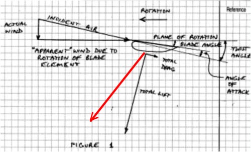
Well that's the way I understand it. 
was working fine... til the smoke got out. Cheers Gill _Cairns, FNQ |
||||
| CanTinker2 Newbie Joined: 21/01/2008 Location: CanadaPosts: 14 |
Thanks Gill From your calculation I get 8.1 degrees for a TSR of 7 and 14 degrees for a TSR of 4. Now throwing calculations to the wind.............. would you think the 9 degrees that I have mounted my blades at sounds reasonable? I would think that a TSR of nearly 7 may not have sufficient torque. I think I have to get this thing in the air and be ready to adjust the angle. John |
||||
| GWatPE Senior Member Joined: 01/09/2006 Location: AustraliaPosts: 2127 |
Hi CanTinker2, You should check out the article by Don Brown on this site for more info. http://www.thebackshed.com/Windmill/articles/DonBrown1.asp cheers, Gordon. become more energy aware |
||||
| CanTinker2 Newbie Joined: 21/01/2008 Location: CanadaPosts: 14 |
Thanks Gordon It was that same page that ended up convincing me to use 9 degrees for my first trial. Don Brown's descrption made the most sense to me so I rounded off his 8.5 degrees to 9 degrees. I had also come up with 9 degress in another of my calculation attempts. At this point I am second guessing myself. I had almost convinced myself to increase the angle, but now I think it is time to get it in the air. Thanks John |
||||
| Gill Senior Member Joined: 11/11/2006 Location: AustraliaPosts: 669 |
John, No I don't think the 9 degrees is reasonable. I think it is workable but that is to say it will not be developing it's fullest rev potential and revs are power (Volts and Amps). You say from your calculations you get 8.1 for a TSR of 7, then minus say 4 deg for Angle of Attack gives a blade tip angle of 4.1 and this is smack in the middle of the 3 to 5 degree range as I think is reasonable. For the less aerodynamic PVC blades, a lower TSR would give say 4 to 8 degrees as reasonable. I am of the opinion(but be warned as nobody has yet agreed with me on this) that it is not totally undesirable to have a prop configuration to just enter stall. Then back off the hub just a little until the stalling is overcome. This way the load is optimised to the prop. Blokes freek out saying "But I will be loosing power", and so they will. But if it is only 1% to 3% by having identified the upper limit(stall) isn't that better than under-designing by 10% or 15%, and sure having a first up working mill but in a blissfully ignorant euphoria of unrealised power? If you're adjusting a car's brakes, who just takes a wild guess at what the setting should be? The mechanic will take the adjustment up to the identifiable point of grabbing then back off just a little for maximum pedal. Why then do we cringe when we identify a little prop stall? So go for a "BLISS" angle if you must. It will undoubtedly work. This is after all just one persons opinion. was working fine... til the smoke got out. Cheers Gill _Cairns, FNQ |
||||
| The Back Shed's forum code is written, and hosted, in Australia. | © JAQ Software 2026 |
