| Author |
Message |
sodes

Newbie

Joined: 26/07/2006
Location: AustraliaPosts: 21 |
| Posted: 10:35am 19 Jun 2008 |
 Copy link to clipboard Copy link to clipboard |
 Print this post |
|
HI all, it always amazes me how many different ways there are to build a windgen some elegant some not so..
This is my first attempt at a furling system i built about a year ago. Some of you may recognise the setup, it is based on the Southern Cross windmills furl setup. It worked quite well, the generator was just topping up an electric fence unit on a car battery, so when the wind got up i would just pull on the cable and the gen would furl and slow right down. Thought i'd throw it on the forum for you all to have a giggle at! Cheers Sodes  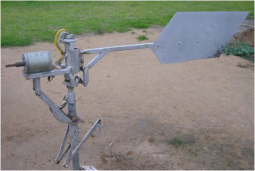
"Do, or do not... There is no try."
-Yoda |
| |
oztules

Guru

Joined: 26/07/2007
Location: AustraliaPosts: 1686 |
| Posted: 12:37pm 19 Jun 2008 |
Copy link to clipboard |
Print this post |
|
Beautiful stuff Sodes.
Odd you should put this up today, I have just finished reconditioning my old Southern Cross pumper this afternoon (built new soft bearings, main shaft etc). For me it is the first time I have had it assembled at ground level, and was interested to notice that it has the setup you have emulated, but also built into the design it also furls like the Piggott type. Up the pole I never thought to test it, but on the ground you get that luxury.
If you look at the Southern Cross rear end you will notice the approx 10 degree tilt of the tail hinge, but unlike yours, the tail attatches to the hinge on a right angle bar on the right hand side (from rear view) of the hinge line. The fan is offset to the left from the head pivot... so they have a auto furling system built in as well as the lovely manual tail furl you have depicted.
I like the design so much, it will be incorporated into my next mill, and replace the brake i was going to design into it. This one has lasted some 50 years or so.
Thanks for showing it
.........oztules
ps perhaps I should take some pics of my SCross mill before I put it back up the pole.
Village idiot...or... just another hack out of his depth |
| |
Dinges
Senior Member

Joined: 04/01/2008
Location: AlbaniaPosts: 510 |
| Posted: 02:37pm 19 Jun 2008 |
Copy link to clipboard |
Print this post |
|
I agree with Oztules, looks pretty nice. No need to be modest about your workmanship.
It's hard for me to see how exactly this furling mechanism works. I'd definitely be interested in a few close-up shots of the mechanism, in various positions of furl-ness.
About a year ago RonB and I did quite a bit of research ( old patents) on furling and vari-pitch mechanisms. I'll admit there are near-infinte ways to solve the problem. And if something has proven itself for over 50 years it can't be bad. Unfortunately I've never seen one of those windmills in real life, so any detailed pictures with short explanation would be greatly appreciated.
Peter. |
| |
oztules
Guru
Joined: 26/07/2007
Location: AustraliaPosts: 1686 |
| Posted: 08:43am 20 Jun 2008 |
Copy link to clipboard |
Print this post |
|
Nice to see the denizens of the north turn up... hi Dinges
In the next day or so I will document the Southern Cross I have on a 4 foot pole in front of the shed. (testing the internals and rebuilding the fan)
It will show the autofurl system (gravity style like Piggotts), but I will have to mount it on it's proper pole to demonstrate the manual furl part.... hence the few days,..... the concrete is still hardening.
I admit I was mildly surprised to learn that the current in vouge gravity furling was just a very old idea rehashed. I was also surprised that even a few locals who have lived with them most of their lives, didn't realise that they self furled.
The beauty of the manual furl is that you can control how much furl to use, ie just run the mill at 50% max etc. The auto furl still over rules the manual set point in this case, so strong wind protection is afforded, even in the semi-furled (don't need too much water today) posn.
........oztules
Village idiot...or... just another hack out of his depth |
| |
sodes
Newbie
Joined: 26/07/2006
Location: AustraliaPosts: 21 |
| Posted: 09:42am 20 Jun 2008 |
Copy link to clipboard |
Print this post |
|
Hi there Oztules and Dinges Im humbled that u liked my handi work there! Yeah I used to work on a station about 50ks North of Conargo Nsw where the famous Conargo Pub is and we had 9 of the old Sthn Cross beauties so I got to know how they operated, bloody tough old things, the boss was telling me one day about one mill that had stood for 40 years without needing any major repairs. Yeah i noticed that the mills self furled a little but i didnt incorporate the offset into my mill design.
Heres a close up shot of the furl mechanism DINGES ..
Heres how it works when in the non furld posn the tails straight and the scissor levery bit is folded up, when u pull on the lever via cable from the ground the lever pushes the disk upwards and the half moon arms are also forced upwards to which the pushrod is connected, the distance is shortened between the halfmoon arms and the tail so the pushrod forces the tail round into a furled position. Aaagh... the tricky bit i found was the pushrod needed to twist as well a pivot on multiple angles this was overcome by using a socket set uni driver bit and a basic swivel piece i made up.
"Do, or do not... There is no try."
-Yoda |
| |
sodes
Newbie
Joined: 26/07/2006
Location: AustraliaPosts: 21 |
| Posted: 10:01am 20 Jun 2008 |
Copy link to clipboard |
Print this post |
|
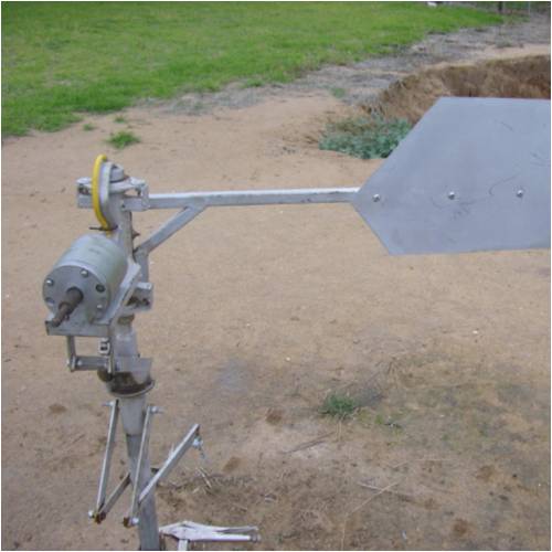
Sorry couldnt fit it all in but it also has a stopper chain there u can see between the tail and the mast. This mill is actually a modified version of my first mill i built when i was 19, it had aluminium cupped blades i folded up, bit of a copy of the tlg windpower dudes blades they really suprised how fast they went! Sorry now im bragging, but the mill had no furling at all just a pretty piss poor shunt reg so i soon pulled it down a did the mod. Looked a bit neater before but not so practical!!
So its been sittin in the shed for while i had intended to dismantle it and go with a new design using an f&p but ive just got motivated again and thought i take some photo of it before i wrecked it. Hope u can work it Dinges!! 
"Do, or do not... There is no try."
-Yoda |
| |
Dinges
Senior Member
Joined: 04/01/2008
Location: AlbaniaPosts: 510 |
| Posted: 12:29pm 21 Jun 2008 |
Copy link to clipboard |
Print this post |
|
Thanks for the close-up pictures and explanation, I think I understand now how it works. Simple but effective system.
I was thinking it self-furled in high winds, but apparently your variant of the Southern-Cross furling system doesn't.
Still, the manual furling is always a nice extra option. I'm still partial to a mechanical brake myself and will implement one on the 10 hp conversion I'm (very intermittently) working on. But maybe I'd have to install an emergency manual furling system as you do. It should be possible to implement this method with the common Hugh-Piggott furling system too.
You can never have too many safeties :)
Peter. |
| |
oztules
Guru
Joined: 26/07/2007
Location: AustraliaPosts: 1686 |
| Posted: 01:35pm 21 Jun 2008 |
Copy link to clipboard |
Print this post |
|
Dinges,
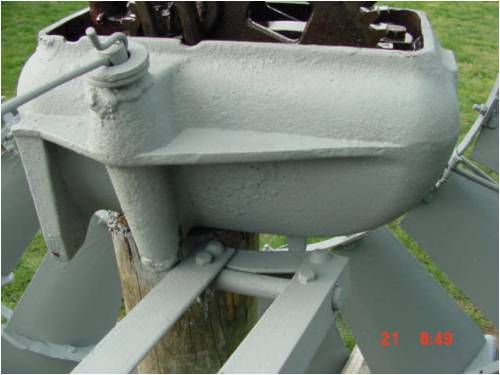
As promised, here is the southern cross original. Note the offset from prop center to post center.

Here we see the closed (no furl) position. Note the right angle bend from the pivot point. This has the same effect as the side tilt on the piggott style. The long pin with the wire through it is about 10 degrees off the vertical, giving it the drooping tail, which is corrected by shortening the tail holding wire.
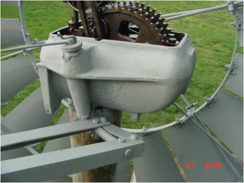
Here we are at partial furl position. Tail is lifting now and there is a few pounds of pressure pulling it back down.
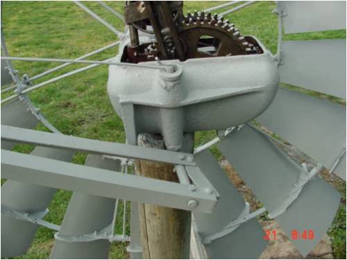
And now at full furl position. Quite a few pounds pulling down now. You can see the two stops as well.
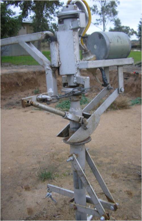
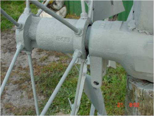
Sadly on the pole I can't show the manual furl as it is intimately involved with the tower head. However, here is the universal yolk and lift forks that Sodes referred to.
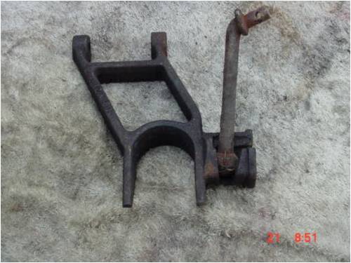
And here is the hinge point on the front of the mill. The yolk bolts to this, and the bar with the ball on the end pins onto the front of the tail bar. When you pull the wire (from on the ground), the yolk forces the tail to furl, but as there is no connection to the pushing disk, it can self furl more than your preset. This allows you to have more mill than you need on a windy day, working well and safely, and then on a calm day, use everything you have got. (an evil person might design with more blade than is prudent, knowing that you can dial in a safety margin at will when you want to, and take extra advantage of low wind days with a fan that is bigger than would otherwise seem prudent for the alternator in question.
I will post the complete system when it is back up the pole. I think it is far better than a brake, because it seems to never have failed over the collective hundreds of years that it has served on just a few properties adjacent to my place. All of these old mills have been through everything that the roaring forties has thrown at them for over half a century (>160kmph winds), they mostly just rust away in the marine environment if not painted every now and then (blades just disappear into nothingness)
........oztules
Village idiot...or... just another hack out of his depth |
| |
sodes
Newbie
Joined: 26/07/2006
Location: AustraliaPosts: 21 |
| Posted: 09:24am 22 Jun 2008 |
Copy link to clipboard |
Print this post |
|
Still looks a pretty tidy unit Oztules, the furl yoke and the ball joint is a nice neat piece of work inst it. They amaze me just how effective amachine they are for something that was designed quite a while ago! Cheers Sodes
"Do, or do not... There is no try."
-Yoda |
| |
Dinges
Senior Member
Joined: 04/01/2008
Location: AlbaniaPosts: 510 |
| Posted: 11:57am 22 Jun 2008 |
Copy link to clipboard |
Print this post |
|
Thanks Oztules.
The way the tail moves about and lifts makes sense. Can't say I understand how the rest of the mechanism works exactly but that's likely due to the fact that it's still missing some essential parts. Looking forward to a similar description/story of you once it's entirely assembled.
It looks to me as the gears are running in an oil bath ? Nice...
|
| |
oztules
Guru
Joined: 26/07/2007
Location: AustraliaPosts: 1686 |
| Posted: 12:36pm 22 Jun 2008 |
Copy link to clipboard |
Print this post |
|
Yes Dinges, the gears are in an oil bath, but also a cunning design is incorporated in the auto oiling system to oil all the different parts above the bath as well.
The reciprocator is 12 inches above the oil. but through a truly cunning ring system, gets oiled every stoke as well. The main shaft has a spiral oiler and catcher which oils the main journal continuously.
These things are meant to last all alone with no decent maintenance. Truly tough machines as Sodes said.
When I give you the pics of the rest of the machine I will include the cunning oiling system.
.........oztules
Village idiot...or... just another hack out of his depth |
| |
