
|
|
Forum Index : Windmills : Working on a 10 hp motorconversion
| Author | Message | ||||
| Dinges Senior Member Joined: 04/01/2008 Location: AlbaniaPosts: 510 |
[quote=Steven]I'm getting the finishing touches on the analysis that is correctly predicting not just voltages, but also power output and required power input. I, too, use FEMM simulations for the starting point.[/quote] Steven, after a long break I finally started studying simulating cogging-torque in FEMM again. As a side-result I found this link that may interest you, as it may be of help in your making a mathematical model of motorconversions; the similarities are obvious: http://femm.foster-miller.net/examples/lrk40/lrk-bldc.pdf more info here too: http://femm.foster-miller.net/Archives/examples/femm40/lrk40 .htm Actually, that LRK model has renewed another idea of mine for conversion: converting a 36-slot motor to a 42 pole generator... Yielding a VERY large polenumber, as compared to normal conversions. I doubt it would be entirely cogless though. First got the idea from this website about 1.5 year ago: http://www.powercroco.de/ Zubbly wasn't too enthusiastic about this idea (he said inserting the coils into the stator would be very hard) but I can't help but think it would be doable. At the moment this project has very low priority (would be nice if I could simulate cogging torque in FEMM first) but still... something I want to play with. Already have a suitable motorframe ( http://www.anotherpower.com/gallery/dinges/kermit_gutted) with 24 stator slots. Could turn that into a 20 or 28-pole generator... especially now that my normal magnetsupplier has started carrying the suitable magnets for it. Argh! And I had decided that this 10hp would be the final motorconversion! Peter. |
||||
oztules Guru Joined: 26/07/2007 Location: AustraliaPosts: 1686 |
Both sets of figures add up. I am not prepared to abandon ULR and co. I/we must be missing something... I can't see what. However, if ULR and Flux etc use these ideas to calculate outputs, there must be a darn good reason. 
I checked the link and see what they are saying, very difficult to dispute. I'm missing something .......oztules Village idiot...or... just another hack out of his depth |
||||
| Dinges Senior Member Joined: 04/01/2008 Location: AlbaniaPosts: 510 |
Oztules, I was just reading this file (http://femm.foster-miller.net/examples/lrk40/lrk-bldc.pdf). Check out the equations for real and apparent power on page 7. They clearly use a factor of 3/2=1.5 for calculating power... 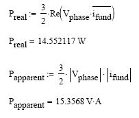
And no, I don't understand it at all. I think I need to brush up on my 3-phase theory. 
On the bright side... I'm finally beginning to grasp the concept of 'leakage inductance' that Flux keeps mentioning. Well, for the transformer case at least. Can't say I fully understand the relevance for permanent magnet generators yet. Peter (living and learning). |
||||
herbnz Senior Member Joined: 18/02/2007 Location: New ZealandPosts: 258 |
Hi Dinges Oztules Dinges is 100% right with 1.73 ratio's and explaination if in doubt about 3 phase go back to phase conditions any 3 phase circuit is 3 separate single phase circuits that can be calculated individualy. The 1.5 that the article you are quoting is approximate equations as stated at the start of the article. Herb |
||||
| oztules Guru Joined: 26/07/2007 Location: AustraliaPosts: 1686 |
Thanks Herb I think I'm sunk with a sine wave. Looking at their calculations, numbers like 15.3568W don't exactly look like approximations. My new suspicion is that they were using trapezoidal waves like we do with battery charging, and this may in fact be a lot more like 1.5 than 1.73. Looks like I may have to surrender with sine, but still clinging on by the fingernails with square and awful waveforms. The waves generated into a diode/ battery arrangement are probably not going to follow the textbook, as they are severely clipped, and more so as we drive harder. With Gordons axial, it is in fact square without the loading and diodes... so peak = rms in his case (as I understand it) With a square wave, the 1.5 should be the figure to use, and maybe why the windmill guys use that figure. Some guidance would be helpful  Also, are you able to take the time to explain how on the motor plate, 400v x 15A = 7.5kw... I only get 6... what else is happening ( in simple terms) Also, are you able to take the time to explain how on the motor plate, 400v x 15A = 7.5kw... I only get 6... what else is happening ( in simple terms)
.......oztules Village idiot...or... just another hack out of his depth |
||||
SparWeb Senior Member Joined: 17/04/2008 Location: CanadaPosts: 196 |
Hi Peter, That Real and Apparent power shouldn't be a mystery if you consider which way the "vectors" point on the AC power triangle. The third side is "reactive power". I'm mixed up by the "3/2" but maybe Herb is right: it's just approximate and the correct factor should be 1.73 or "square-root-of-3". I was kidding the other day about K.I.S.S., but I'm so terribly impatient for you to just test the iron loss in your motor conversion that I'm having trouble waiting. The thought of you building a VFD drive, calibrating it, devising a coupling to your conversion, and then getting the test under way gets me chewing up my keyboard. I must be having trouble getting your attention on this, so I will be blunt: you can conduct the test with 10 Euros of materials and it will take about 20 minutes! 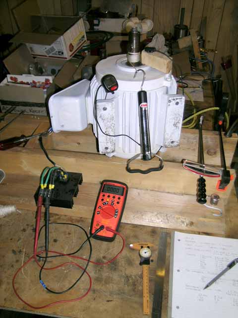
In my photograph above, I show all the materials I used to test the Toshiba conversion. At the lower left, you can see the black heat-sink that holds some little rectifiers - the measured output is DC. On the shaft, I have wound a string a few dozen times. Hooked on the string is a scale. Also beside the shaft is a bicycle speedometer, which I use as a RPM counter. The display is on the left of the shaft and the sensor is on the right side of the shaft. The multimeter reads the DC voltage only - the whole test is conducted open-circuit. By pulling on the string at a relatively constant force, the velocity and voltage are fairly constant. Watch these carefully, and/or set the devices to record the maximum values. Write down the Force, RPM, and VDC for multiple tries until you have covered a range of speeds that you can perform consistently. That's it! Nothing left but a bit of math: Q=F*r (the force times the radius of the shaft) P=Q*w (the torque times the rotational speed) "F" varies with "w" so you need to keep a table of values and then plot carefully. Then build a curve-fit to the data. I suggest a logarithmic function because it has worked for me 3 times, though I do not know what the function actually should be. For the Toshiba, a linear curve-fit was as good as a logarithmic one. Here are the curves for the GE, as I added magnets and measured the effect. 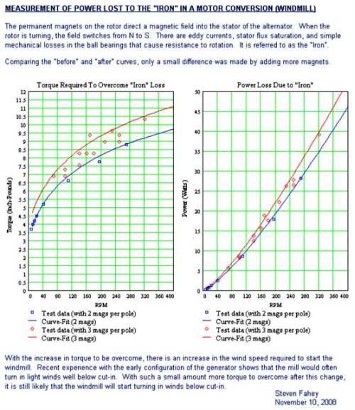
Steven T. Fahey |
||||
| Dinges Senior Member Joined: 04/01/2008 Location: AlbaniaPosts: 510 |
Thanks Herb. [quote=Oztules]My new suspicion is that they were using trapezoidal waves like we do with battery charging, and this may in fact be a lot more like 1.5 than 1.73. Looks like I may have to surrender with sine, but still clinging on by the fingernails with square and awful waveforms. [/quote] Yes, exactly what I was thinking... If you look at the waveshape on page 5 ( http://femm.foster-miller.net/examples/lrk40/lrk-bldc.pdf) you can see the waveshape they drive it with (Iphase, red line). Also this remark in the conclusion may give a hint: "The above represents a somewhat rough crack at analyzing an LRK motor designed to have a trapezoidal back-EMF and driven by a two-phase-on drive." That is hardly like the real 3-phase sinuso�d power that the local utility pumps into the grid... and for which standard/simple 3-phase power theory is valid. For an approximation/rough crack they certainly show a lot digits: up to the 5th decimal. I think the writers need a crash course in the concept of 'significant digits'. Their numbers (15.xxxxx W) suggest an accuracy which simply isn't there. [quote=Oztules]With a square wave, the 1.5 should be the figure to use, and maybe why the windmill guys use that figure.[/quote] That's about the only explanation left, and I think that's the correct one. Charging batteries via rectifiers we are dealing with anything BUT sinusoid waveshapes: 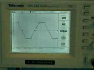
So basically the entire standard 3-phase theory, which assumes perfectly sinusoid waveshapes, doesn't apply to our special case of charging batteries... About the nameplate rating (400V and 15.4A = 6.2 kW != 7.5kW)... I think for a 3-phase system power P = 1.73*U*I = 1.73*400*15.4 = 10660W (10.7kW electrical input); with 7.5kW mechanical output, yielding a conversion efficiency of 7.5/10.7 = 70% Hopefully Herb can clarify/confirm. Peter. |
||||
| Dinges Senior Member Joined: 04/01/2008 Location: AlbaniaPosts: 510 |
Steven, I won't be actually *building* a VFD drive; already have a suitable one (3phase 400V input, 2kW) and a suitable drive motor. Just need a few wires to hook it up and some sort of coupling (thinking of a piece of hose and hoseclamps around the shafts) to mechanically couple the motor and the generator. You've already explained pretty well how to determine iron losses with nothing but a piece of string and a stopwatch, but I don't have a proper spring scale. I do have a few kitchen scales but they're only of use in a De Prony-brake setup. And as I need to measure these things anyway once the motor is wound... I'd rather do it once and properly. Apart from that, last week I removed the rotor from the stator again in preparation for rewinding. Inserting and removing the rotor causes some scratches (no real damage though, but I *am* glad the magnets are totally cast in epoxy resin. If not the nickel plating of the magnets would definitely have become damaged, with probably long-term corrosion as a result) and I want to keep the inserting and removing the rotor to an absolute minimum for this and other reasons (every insertion/removal is taking a risk; things can go wrong). I'll be inserting the rotor once more, once it is rewound, to test whether my cut-in RPM is correct; then remove rotor, varnish stator and re-insert rotor, this time for the (hopefully) last time. And then build up a measurement setup to measure RPM/V, cut-in RPM, charge curve, iron & copper losses, etc. So you'll have to be patient a little more. 
...don't you just love cliffhangers...? [quote=Steven]Then build a curve-fit to the data. I suggest a logarithmic function because it has worked for me 3 times, though I do not know what the function actually should be.[/quote] You may find this article interesting; it deals with determining iron loss in brushless DC motors. The Steinmetz equation shows that iron loss doesn't vary linearly with frequency (RPM) as I had thought so far: 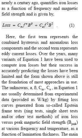
Source: http://www.magneticsmagazine.com/images/Archived%20Articles/ JJ08_Infolytica.pdf They also mention 'Epstein' tests and ringtests. I'm slightly familiar with ringtesting; in the near future I'll try to study up a bit more on those Epstein tests. I know the local motor rewinding company has equipment to determine whether the stator losses are still within specifications. If the losses fall outside specs they apparently don't even bother to rewind. I'm curious how they actually measure this. [quote=Steven][...]gets me chewing up my keyboard. [/quote] Patience is a virtue. In the mean time: Bon app�tit 
Peter. Edit:[quote=steven]I must be having trouble getting your attention on this, so I will be blunt: you can conduct the test with 10 Euros of materials and it will take about 20 minutes! [/quote] I didn't miss it the first time, but as the generator had already been disassembled before I posted my accurate RPM/V results it was no longer an issue. Hence. BTW, it can be done even more cheaply: ditch the spring scale and use a small weight instead (set the motor horizontally). Let gravity pull the weight down. As F=m*g you know your force and can derive torque. As a bonus, you won't have to pull yourself, trying to 1)keep pulling force constant 2) read the spring scale 3) start/stop the stopwatch. Vary weight to gather more datapoints. |
||||
| KiwiJohn Guru Joined: 01/12/2005 Location: New ZealandPosts: 691 |
[quote]If the losses fall outside specs they apparently don't even bother to rewind. I'm curious how they actually measure this. [/quote] I presume iron losses become excessive when inter-lamination insulation begins to fail? This would show as increased effort required to spin the motor open circuit and by heating of the laminations when in a pulsating magnetic field. Perhaps they uses tests based on something like that? |
||||
| herbnz Senior Member Joined: 18/02/2007 Location: New ZealandPosts: 258 |
hi The reason I mentioned approx was that at the start they said some equations are approximate ??? I have worked in a university with real academics that write these articles, they do tend to complicate issues not always correctly either. I never spent a lot time on this one so better not say much, but Dr Chalkos is full of errors. Ok power I see Dinges has started to explain but I will do again first the motor is 3 phase the values given are line conditions that exsist at the input it is delta connected with 400v 15a first using line conditions the formula is 1.732*V*I = VA (this formula is the same star or delta) note VA not Watts We get one back Dinges here. Therefore VA =10392 if pf is .8 watts = .8 * 10392 = 8313W eff = 7500/8313 = 90% Ok if we treat it as 3 separate 1 phase Delta phase V = line V = 400V Phase current = Line I /1.732 = 8.6A Total VA = 3 * 8.6 * 400 = 10320 more less as in line conditions rounding is the only diff Herb ps Note 7.5KW is shaft power ie output Another point note you talking RMS Peak the 1.732 nothing to do with this its a build in factor in line conditions formula to actually convert back to phase the phase calculation is the basic way really.the values are assumed to be RMS . Again if in doubt measure phase conditions calculate then * 3 |
||||
| herbnz Senior Member Joined: 18/02/2007 Location: New ZealandPosts: 258 |
|
||||
| Dinges Senior Member Joined: 04/01/2008 Location: AlbaniaPosts: 510 |
HerbNZ, Thanks for the explanation on calculating power for that 3-phase motor. Will have to stay more alert on properly differentiating between VA and W in the future... Taking cos-phi into account dramatically changes the efficiency of the motor. [Quote=KiwiJohn] I presume iron losses become excessive when inter-lamination insulation begins to fail?[/quote] That would increase the eddy-current part of the iron losses, yes. I figure that's also the reason why professional motor rewinders are careful when putting the motor in the burn-out oven (to burn away the lacquer/varnish): too high temperatures may damage the iron insulation? Simply tossing the motor in a roaring woodfire to burn out the varnished copper wires (as I've heard some motorconversion builders do...) could seriously damage that insulation layer between the laminates and increase iron losses. And extra losses is the last thing we need in a windturbine application. Peter. |
||||
| The Back Shed's forum code is written, and hosted, in Australia. | © JAQ Software 2026 |
