
|
|
Forum Index : Windmills : motorconversion efficiency measurement
| Author | Message | ||||
| Dinges Senior Member Joined: 04/01/2008 Location: AlbaniaPosts: 510 |
That's correct Gordon, I did that for mechanical reasons (attaching the stator to the rest of the generator). In the mini axial flux that wasn't much of an issue as it only added 1.5 mm to the airgap, but in the bicycle genny it was a mistake to use a much thicker carrier plate. Finally have your axial flux dual-rotor simulated with FEMM. Will post it in this thread so as to not dilute other people's threads. N32 magnets, 25x12.5 mm, 10 mm rotor plate thickness (AISI 1006), 3mm airgap, 2 mm between magnets (I know in your case it's really a wedge from .5-4mm, but can't account for that in 2D software; chose a compromise value). See image below. Airgap flux density is slightly below 1T. There's relatively little leakage from a magnet to the next magnet. 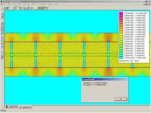
High resolution image can be found here (click on magnifying glass for full details): http://picasaweb.google.com/motorconversion/Temp/photo#52392 03993718676242 This flux density is about equivalent to a 'normal' axial flux (N40 50x25x12.5 mm magnets) with an airgap of about 9 mm; see this simulation: http://www.anotherpower.com/gallery/album89/axial_flux_airga p_sim_9mm I can make the FEMM files of your generator available to you if you want to play around with the software yourself. Peter. |
||||
| GWatPE Senior Member Joined: 01/09/2006 Location: AustraliaPosts: 2127 |
Hi dinges, That is very interesting, that the fields are very neat and uniform. The simulation in the iron return path shows what occurs IRL. I am interested to see the simulation of a single side by itself and with the strongest available magnets N55 of the same size in the complete configuration. My unit produces a loaded 28V@4A from 187 turns at approx 150 flux transitions per second from each of the 4 phases at the maximum furled wind energy with the 1T field. I suspect that stronger magnets will lower the rpm at which the max 4A can be extracted, or increase the power output for the same current at the same rpm. This same copper amount could probably produce 1kW into 48V with a stronger magnet set. The stronger magnets would probably proportionally increase the efficiency as well. This may be something for the future when I finish F&P testing. Gordon. become more energy aware |
||||
| Dinges Senior Member Joined: 04/01/2008 Location: AlbaniaPosts: 510 |
Gordon, I was going to suggest to simply extrapolate the results: N32 has a surface flux density of 1.14 T, the flux in your generator was 0.95 T, so .83 times surface flux density. N54 has a surface flux density of 1.54 T, so using the same ratio we'd arrive at a gap flux density 1.54 * .83 = 1.28 T Just to verify for myself whether this extrapolation stuff was accurate I decided to resimulate it. Not much work as I already have the model, but was the first time I created a new material (N54) in the materials library. After simulating again I got a flux gap density of 1.22 T (so about 5% error compared to linear extrapolation; not too bad). It appears that going from N32 to N54 would give you a 28% increase in gap magnetic flux density (1.22T/0.95T). I didn't bother to upload the new simulation image; it's exactly the same as the one above for N32, just with slightly denser flux lines. The simulation for the single rotor verion (N32) is below: 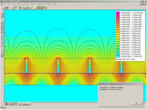
(high resolution image can be found here: http://picasaweb.google.com/motorconversion/Temp/photo#52395 15225827240162) As was to be expected, a lot more flux leakage in this case, with the magnets so close to eachother. Hope this helps, Peter. |
||||
| GWatPE Senior Member Joined: 01/09/2006 Location: AustraliaPosts: 2127 |
Hi dinges, I thank you for FEMMing for single rotor and recalculating for the stronger magnets. The single rotor shows a large amount of flux lines in an area where they cannot be used. The simulation is a little different to what I found IRL. I measured flux escaping from the iron backing in the single rotor version. When I brought the 2 rotors together to the closed 3mm spacing, the magnetic fields no longer escaped. The uniform magnetic field in the closed arrangement confirms the waveform I measure IRL. In my design, the coil is passed through a constant magnetic field, so there is a constant emf produced at a constant angular velocity. The emf reverses as the magnetic field reverses. This is why my design produces a close square wave output. The constant emf produces constant current into the load, so copper losses are a minimum. This design would probably not work as well with an iron core design. I measured that >90% of the waveform produced a constant emf. I concluded that a slight improvement may have been gained with a segmented magnet arrangement. I could not justify the additional costs though. I doubt that the designs with much bigger coils and wider air gaps with a non constant magnetic field would have the same benefits I found with the constant magnetic field, at least when a battery, or capacitive load was applied. I hope others can make use of the information that has been presented thus far. Dinges calcs with the simulator back up my experimental findings. This is a good sign. The FEMM shows that as the air gap is reduced, magnet spacing on each rotor can reduce. I suspect that for an axial flux design, some gains can be made in reducing the air gap. The output power seems to increase with more copper, for the same amount of magnet. This is all interesting stuff. Gordon. become more energy aware |
||||
| Dinges Senior Member Joined: 04/01/2008 Location: AlbaniaPosts: 510 |
I think that can be easily explained. Remember, FEMM is a 2D package; we're looking here at a cross-section of your rotor. I recall that in real life your steel backing plate is just a ring that is only very slightly wider than the magnets (ring was 27mm wide, IIRC, vs. 25mm wide magnets). I think what happens is this: in the single-rotor configuration, the flux lines leave the exposed part of the magnet, go through the air and a part of it bends back to the rear end of the magnets (as opposed to going to the neighbour magnet): in 3D, imagine part of the flux comes out of the screen and goes down through the air in front of the monitor, then goes back into the screen and goes upward (in the simulation plane) to the back of the rotor. I think that is the magnetic flux you detect on the backside of your rotor plates. When the 2nd rotor plate (ring) with magnets is added, the flux goes straight from one rotor to the next, without 'bending back' on itself as in the previous case. I doubt there'd be really any flux leaking out the back, as the iron backing plate is far from saturated. If there was *real* saturation of the rotor iron, then in both cases there should be magnet flux leaving the backside of the rotor ring: both in the single and dual rotor situations. With a real 3D package this should be easy to visualize. It can be made visible in 2D too, but I'd have to make another cross section, 90 deg. off, and re-simulate; I'll leave that as an exercise for the reader though... ;) That's the nice thing about FEMM: after playing around with it you get a bit of a feeling of how the flux lines behave in real life. It may not be a 100% perfect simulation (if only for being 2D; though I'd not even *dare* think how long a real 3D simulation would take, considering this PC takes 5-60 minutes for just a 2D simulation...), but it's a great learning tool. |
||||
| GWatPE Senior Member Joined: 01/09/2006 Location: AustraliaPosts: 2127 |
Hi dinges, I had thought the field was returning back through the air to the iron. This was hard to prove IRL. I think this exhausts my I/O here. Gordon. become more energy aware |
||||
| The Back Shed's forum code is written, and hosted, in Australia. | © JAQ Software 2026 |
