
|
|
Forum Index : Windmills : furling revisited?
| Author | Message | ||||
| KiwiJohn Guru Joined: 01/12/2005 Location: New ZealandPosts: 691 |
Whiskey, I find your system very interesting though I do wonder at a couple of aspects of it. 
For one you say that the blades must move the same amount or vibration would be bad, maybe, but then I think of a helicopter rotor and the discovery by Juan de la Cierva. He discovered his autogyro was much more stable when the blades had flexible roots, IIRC he discovered this on a model where the blades were attached by rattan to the hub. Many helicopters (but not all) have fully articulated blades which have both flap and drag hinges allowing the helicopter blades to both cone and to take up a position in the the rotor disc according to the instantaneous forces. In your system you have the flap hinges but not the drag hinges and I venture to suggest that if they did have flap hinges it would be easier to avoid vibration, there would be less bending stress on the blades (and blades could be lighter so reducing forces further) and blades would be able to take up a position of equilibrium. I think also that the mill would more quickly respond to variations in wind direction, with the blades coupled as you have a change of direction would tend the entire blade disc to tilt up, or down, under gyroscopic effect but in a fully articulated system the blades would follow a path according to the forces acting on them and they would not resist yawing of the mill. Helicopter blades are indeed quite different to wind turbine blades... 
Well, those my thoughts for what they are worth.  |
||||
whiskey Newbie Joined: 19/06/2007 Location: IrelandPosts: 21 |
Taking your last comment first, helicopter blades are different to wind turbine blades, sums it up and both are used very differently. Wind turbines do not have a cyclic arrangement that allows the blades to pivot about the horizontal axis, they are fixed to this and only rotate about it. It is desirable to have all blades bend at the same amount to keep vibration low, when one blade bends more than another they follow a different track for a short period of time and this induced vibration causes all sorts of problems to the machine other than just the blades themselves. Accelerated bearing wear and so on. Reducing the vibration will also reduce noise and stress on the blade. My material choice for wind turbine blades has always been wood. No composite material has yet been invented that has the resistance of wood to loading due to flex caused by the wind. Many different types of aircraft have advanced blade material composition but remember they do have a life span and are replaced. We dont have the luxury of a means to examine a wind turbine blade after each daily or nightly flight. So we choose a material that natures gives us and that man has never surpassed. I use clear white american ash for my blades and it carves nicely. I dont know what you mean by drag hinges and drag is something I dont want. Also remember wind turbine blade and helicopter blades are light years apart and neither can be scaled to work for the other application. The Reynolds numbers on a helicopter blade is in the millions whereas a wind turbine blade is typically in the 500,000 range. Many helicopter blades are also symmetrical and that is of no benefit to a wind turbine. We also run higher solidity than aircraft blades too. My blade mounting has been flying for many years and in areas of high winds, there has not been any failures. Without mounting them like I have the vibration was very high when ran on a test bed and had me head scratching for a while until I could find something that would work, be reliable and fool proof if any of its components should fail. And if I ever get a coning failure, the machine will always default into fully coned and safe from runaway. My blades cannot tilt up, down or side ways, they can only cone out and behind the machine. The axis of the machine never leaves the horizontal plane, it is fixed horizontally and can only rotate about the yaw bearings. It is wind speed pushes the blades into coning, not centrifugal force. The main thing is to visualise is the gyroscopic effect is not constantly shifting from the head wind, to the side, or top. It is staying into the wind all the time regardless of wind speed and direction. Hope this helps and I know its hard to picture without seeing it. |
||||
| KiwiJohn Guru Joined: 01/12/2005 Location: New ZealandPosts: 691 |
I apologise Whiskey if I did not make myself clear. Helicopter blades are indeed quite different to wind turbine blades but that does not, as you say, sum it up. Helicopter blades have to operate in various modes between hovering and forward flight but they also have to cope with a total change of flow direction through the rotor disk when they enter auto-rotation, auto giro blades are in this mode all the time. During auto rotation air flows up through the blades and in this state they are quite similar to a wind turbine and it was for this mode that Cierva was trying to accommodate when he 'discovered' full articulation. The point about an articulated blade mount is that each blade is free to follow a path where the forces acting on it equalise, there is nothing acting against the forces that are tending to push the blades from their nice circular path as the blade can follow the path that suites and hence nothing is transferred to the hub to cause vibration or even to bend the blades. Fully articulated helicopter blades support the entire weight of the machine, its crew and any cargo yet the blades are really not very strong, they do not have to be strong as they are not fighting a force that would restrain them in a particular position. I realise how familiar you are with helicopters when you state you dont know what a drag hinge is, (though I have to admit that I may have caused confusion by using the wrong name which more correctly is the 'lag hinge') quite simple really, it is a hinge with an axis at, or near, to right angles with the flap (i.e. cone) hinge you already have. A lag hinge allows the blade to advance and retreat according to the forces acting on it. In a helicopter with articulated rotors and in forward flight the lag hinge allows the blades to advance on the retreating side and retreat on the advancing side and so reduces the rolling moment of the rotor disk. Not all helicopters have articulated rotor systems, there are also semi-rigid and hingeless systems. You say the axis of your turbine never leaves the horizontal plane and I believe you, you have bolted it down and you permit no laughing in church in this regard. However whenever the mill yaws there is a tilting force and you have made your machine strong enough to accommodate that. With full articulation of the blades you would not have to fight this force. I am the first to admit that I am not an expert in this particular field but I can confidently claim that I know enough to state that a fully articulated blade set for a downwind wind turbine would make an interesting experiment. |
||||
wind-pirate Senior Member Joined: 01/02/2007 Location: CanadaPosts: 101 |
This picture is a parris dunn 1950's era. The generator lifts up in a strong wind to furl. Ron 
THE Pirate. stealing wind & solar energy is fun |
||||
| whiskey Newbie Joined: 19/06/2007 Location: IrelandPosts: 21 |
Morning Gents, The helicopter blade comparison is unhelpful in this exchange as the operating regime is much different to a wind turbine. Not only is the wind speed/Reynolds numbers far apart, the mechanism used on a helicopter to control its blades is not something I would never place on a wind turbine where we do not have the service and inspection routine that aircraft have. Making any wind turbine more complex to gain any advantage will ultimately lead to it failing where a more simple and robust machine will continue to fly and produce power. Unless you can examine a complex machine at x hours as with an aircraft it is a non runner for me, and who wants to take a wind turbine down every x hours to inspect it? The best info you will get on blades more suitable to us are not on helicopters or aircraft, but on human flight machines. There is no published research for the most part of this that I know of, other than the blade profiles and that is what I have used for my own blades. The fact remains that any blade on a wind turbine or aircraft when ran out of line and not tracking the same path as the other blades will induce vibration. I wont mention helicopters here because they are too far from our machines and we do not use highly flexible blades. Even the large megawatt wind turbines are now gone from gearboxes to direct drive PMG in order to reduce weight, complexity, down time and noise. I can see what you want to do and for my money and time it is not something I would consider. I dont want to sound like I am putting your idea down, and welcome anyone who wants to try something new. My own backround in wind turbines is 19 years getting to this end and my design is proven and I wont change it unless something breaks or some other reason makes me do it for improved performance. It is hard to make any improvement to even an upwind machine where the blades are not concerned and the engineering and manufacture is of good quality, they have developed to a level where any changes will take years to prove and few will do that, even a home builder. Advances in PMG will give even a home builder 90% efficiency or 92% if they take time and be fussy. The best gain anyone can hope to achieve with a home made wind turbine is in the blade design. Specifically the blades used on home made dual rotor machines have very inefficient blades and lots of energy is not being captured. The fault there is squarely on the blade design and not on the PMG. The power characteristics of a PMG with laminations and many aircraft blade profiles chosen by home builders work well(ish) with the laminated core. But when you move to dual rotor the power curve of the PMG and existing blade profile people carve wont work. I have been vocal on this for many years on fieldlines IRC along with another guy (BobN) who is now RIP, and to date nobody is taking the cause of the problem and fixing it. The blades stall at higher speed, something that tells us there is a major problem there. Not enough lift at speed and people report the PMG stalls the blades. NO!....the blades are not providing enough lift and adding resistance into the line or opening the air gap puts a band aid on the problem and makes a 90% efficient PMG, now grossly inefficient. Fix the cause, not the effect. I think most people wont spend the time to carve a proper profile and just want to put a machine up that will work. But their idea of work means, it turns when the wind blows, mine is a tad different :) Keep it simple, strong and efficient. The old machines had excellent mechanical design and are time proven. Newer commercial small scale machines wont last anywhere near the old Dunlites and Jacobs. But they could do with an alternator rejig if someone is rebuilding one and gain some extra watts. Apologies to the thread starter for driving the reply well off your question! |
||||
| KiwiJohn Guru Joined: 01/12/2005 Location: New ZealandPosts: 691 |
Matthew 7:6 |
||||
| GWatPE Senior Member Joined: 01/09/2006 Location: AustraliaPosts: 2127 |
Sorry tinker, but I wish to add a bit before the thread goes cold Hi whiskey, I have a dual rotor axial flux mill and an F&P mill. I am using Lakota blades, those designed for an iron cored machine, on my dual rotor mill. The stalling of the blades you mention is probably more caused by a loading problem. Most applications have a battery load. This tends to overload the mill at the higher power levels. This is most likely why the blades stall. My dual rotor mill with maximiser allows the alternator to follow the maximum power curve of the wind, up to furling {I have a side furling system}, into a battery load. After furling the power output flattens OFF. It hardly matters what happens after furling, as mill preservation takes precedence. I see the loading is as much a key as the blades. Do you have any data to back up your claims? Some output power v wind velocity giving rotor capture area would be of use. Gordon. become more energy aware |
||||
| whiskey Newbie Joined: 19/06/2007 Location: IrelandPosts: 21 |
kiwijohn, if you dont want to be part of a discussion please dont dump on the thread. Gordon, The alternator cannot stall blades because it is not the prime mover, the blades are. And if you are getting stall in higher wind speeds it means the force from the blades is unable to turn the alternator fast enough. If the opposite were true, in other words an aircraft engine being too big or too small for a given prop, most aircraft props would either have lousy take off or lousy cruise. This is considering a fixed prop like we use. The aircraft guys design a blade not for cruise or take off, but a compromise between both as it is not possible to get both in a fixed prop. Most home brew blades are built for take off and the blade loading is best at take off or low wind speed. That is the best way I can put it. You could also look at it as putting a higher HP engine into your plane and expect the same prop to work as good as the old one. Loading of the blade is progressive and that is why you see distributed twist, all are calculated and not done by eye. We must also use a higher solidity rotor and lower reynolds number blade, only then will you see an improvement in performance. If you want to progressively load a blade you could actively alter its pitch for highest performance. But you will still need a taper in each plane and distributed twist, the build will be a tough one though. The research by Selig, Larabee, Atkins, Somer and more all show how its done. All the blade profiles are freely available and all are ideal for use in small scale wind turbines. |
||||
oztules Guru Joined: 26/07/2007 Location: AustraliaPosts: 1686 |
Interesting commentary Whiskey. I am sure you must be right, but my recent experience with the AWP seems to muddy the waters some. After it shed it's glass blades we hurriedly chewed out a new set out of a solid log of wood with a chainsaw. The results so far are pretty interesting. The machine has slightly later startup, but better power overall. Its furling has changed so that in the latest blow (60 knots or more for a day) it was putting 1.5kw into the batts and dumpload in furl. It has less start torque for the iron loss to be overcome (only just but noticeable), but as soon as it starts, it seems to run more freely. It has a lower noise quotient now, and in full furl, is considerably quieter than the AWP blades.... without a lot of the luffing/airplane noise the AWP blades make when they are furled or are dancing around with the furling system. The AWP didn't ever get much over 1.2kw in the furled position, so something (apart from the noise) has altered here. In the general range, it seems to be putting more into the batteries than before.... which was too much anyway... The chainsawn blades seem to be working so well, that I think the owner has just turned down an offer of free replacement blades from AWP, as he thinks these are putting more coulombs into the batteries than before. Now the AWP blades are/were very nice looking blades with all the rich twists and deep root etc, but it didn't translate into better blades on this alt. Perhaps on a neo dual axial, it would be different. I suspect you are familiar with the AWP profile and pedigree. On a different note: I am intrigued with the mechanics of your downwind "furling" technique. I would appreciate it if you could get time to take a picture/s of it. I am not that happy with the traditional furling technique as shown on otherpower. Mine spends too much time hunting about the place, I would like to have something spending more time in the "zone" so to speak. I recently rebuilt it for a longer offset, now 8", which makes it hunt even more, but at least furl out of the damaging winds easier. Adding more weight to the tail seems to make little difference, so another rebuild looks imminent. Nice to see you taking an active interest on the board too. .........oztules Village idiot...or... just another hack out of his depth |
||||
| whiskey Newbie Joined: 19/06/2007 Location: IrelandPosts: 21 |
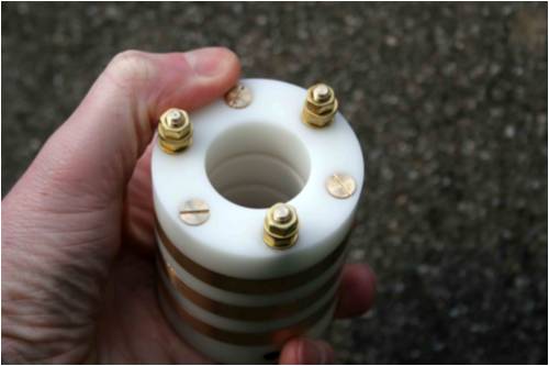
Hi oztules, I had to search around for your AWP hacking and chainsaw whirling, looks like it was a good time in the making too! What are your blade tip profiles now and in comparison to the AWP blades? AWP had poor welding on their early machines and their blades were had poor QC, many blades left the factory with filler and rather sloppy workmanship. Each wind turbine will have a unique blade made for it and there is no catch all as you will have guessed by now. From what I remember the AWP alternator was physically large for its output and that is likely why it done so well in many parts of the world when annual energy output was logged. I have pictures some place of the poor weld on the alternator. The factory took a lot of risks back then and I have yet to see a new model to see have they cured the old mistakes. I dont have an pics of my machines at the moment, but will take some of the next build. As a taster, here are some slipring pictures. 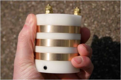
The hunting you are getting could be a too short tail boom, or not enough area for the tail. Altering the weight on the tail or alternator will only change the furling time. increasing the offset will make the machine easier to furl, i.e more moment available. If money and time was not a factor, some active pitch control would be nice :) The AWP machine would probably be my machine of choice if I had to buy one. The likes of Bergey and Whisper machines do not last in our climate. If you build a slower speed wind turbine, it is easier to get good energy harvest on low cost, high pole count PMG's. It is a little wasteful, but saves an aweful lot of fussing over blades. N35 and N38 magnets are cheap now and a 31 or 34 pole alternator would be nice and spin very slowly, under 200RPM I guess for multi Kw. |
||||
| GWatPE Senior Member Joined: 01/09/2006 Location: AustraliaPosts: 2127 |
Hi whiskey, I do not follow the first sentence. The alternatator certainly can stall the blades. When I short the output of my axial flux mill, the blades stall and the alternator slows to a few rpm. This is how I electrically brake my mill. This may not work on all iron cored machines. In the second sentence. If the alternator load is too great, then the blades may reach a point where stall occurs. Adding more blades will increase torque at the expense of increased drag. If adding more blades is an improvement, then it suggests to me a mismatch with the loading may be the cause. I suspect that the cone type furling you utilize works best with a particular blade configuration and rotor rpm. Matching the form drag loading of a blade to the centrifugal forces to achieve furling will be easier with a large blade area and low rpm. Modern Neo magnets have high power density, so allow low rpm machines to still produce useful power. PS I see you have replied to Oztules, I have 2 windmills. Of prime importance to me is maximum power output for the available wind at the time. I have tackled the bottom end of the power spectrum with excellent results. I do not think that the alternator/blade combination can load the wind correctly, in any stand alone configuration. I have seen the best match with some electronic wizardry to help out at the low wind power end. I have a wide variety of people see my setup. More people are wishing to set up windmills in less than optimal sites. The low wind energy in suburban residential home locations is likely to drive the technology towards quieter, low rpm machines, that are hopefully small. Any proven technology that allows more efficient harvest of the wind energy is a plus. It is not until you do the calcs on the avalable wind energy and how much is harvested, that you realize how much just goes past. I think I am doing well to get a max 30%. The slip rings on my mill are insulated with the high temperature phenolic fibre reinforced type insulation. Is the white insulator on yours, Teflon? The slip fingers and brushes I found were the important components in the assembly. Gordon. become more energy aware |
||||
| oztules Guru Joined: 26/07/2007 Location: AustraliaPosts: 1686 |
Thanks for that Whiskey. I will look forward to your next iteration of your machine. Slips look good, but we have done away with the AWP ones altogether. Better system for it I say.... but we have only 240v to run down the tower, so skinny wires can take a lot of twist if they have to (15A extension cord does nicely). These stories may be of interest to you regarding the blades and the AWP saga. awp Fixing the stator of the AWP Making my blades with the chainsaw AWP blade story more AWP fun and still more AWP stuff The blades are a simple profile 3 deg at the tip 6 halfway etc... linear. Thickess is around 1/8 cord. Cord is about 4" at the tip up to 8" about 16" into the radius.... 4m blades. The AWP is the same sort of thing with 10" wide timber to match the original blade holders.... otherwise it would have been 8" probably. As the power in the inner third is fairly marginal, we made no attempt to capture it.... I feel more would be gained from a few extra inches of radius, and a bigger magnets and wire, rather than chasing small gains in finessing a smaller blade.... but thats because I am not a purist I guess. All the AWP problems aside, if I were looking to buy a machine, the AWP would be it..... and I am comfortable that I can rebuild anything that went wrong anyway if they haven't improved quality of build now. Great design with little ferrites. We didn't really need the Neo's to make great windmills. I am toying with the pitch control as well, so if you have any proven favourites, then speak up.. ..........oztules Village idiot...or... just another hack out of his depth |
||||
| Robb Senior Member Joined: 01/08/2007 Location: AustraliaPosts: 221 |
A very interesting point about the autogyro Kiwijohn. I'm not sure every one picked up on that one though. |
||||
| whiskey Newbie Joined: 19/06/2007 Location: IrelandPosts: 21 |
Hi Gordon, Of course the blades will stall when you short the output of the alternator, but thats hardly normal running conditions :) When you have a fully loaded blade and alternator, both are working at the max design load and the outer portion of the blade is where all the work (lift) comes from. When a blade starts up, all the lift comes from the root and as speed increase the area of max lift moves out the blade towards the tips. I have pics and possibly animations showing how this works. I use a disc brake on my machines and do not short out the windings at all. I dislike heating the coils like that and want a fool proof way of keeping the machine stopped when it is about to get stormy or if I am away for a few days. You could carve a few sets of blades for your own machine of the same diameter and with a small change to the profile, the effect on some changes can be amazing to see, getting the balance right for all conditions has me still looking for the perfect blade after all these years. The research is interesting and only in the last years has more data being released on newer blade profiles for human flight and low speed aircraft such as the new ultra class. What you could try to get some more power is to change how you wired the coils and have them switch from star in low wind speeds, to delta in higher wind speeds. I do this by monitoring the frequency from the alternator and switch over via relay to delta. Be sure to have some hysteresis control in there to stop the relay going to god prematurely. I used delrin for the insulator in my slip rings and my brushes are a custom blend of carbon, graphite and copper. I never found off the shelf brushes to transfer power efficiently, last a long time and and self lubricate without leaving residue and scoring on the ring surface. Brushes are a science all of their own. oztules, snap, I too use 240vac from the coils, its an efficient way to get power across and lower cost on the wiring down the tower. I will cjeck out your links when I get the time. What blade profile did you use on your homebrew blades? If you are feeling adventerous, try the USA35B or Supercub wing profile, it is a reasonably good low speed profile. I design for low and medium wind speeds and uninterested in the high winds and high speed machines, none ever last any time at all. If a guy was on a budget and still wanted pretty good power and low speed it can be done using either ferrite or lower grade neo, just use plenty poles and your RPM is now way down and less fussing on getting lift at high speeds. The range between startup and max output is much smaller than that of high speed machines where compromise is much more apparent. 3 to 4x the RPM v 3 x 10 times. The problem with pitch control, is on order for it to be effective it needs to be electronically active rather than mechanically reactive. Getting an electronic system reliable and fool proof in case of failure is difficult. The mechanism to move the blades is not that difficult, but the electronics give me headaches trying to figure out how best to build in a system that allows the blades to be fully furled/flat pitch into the wind in case of controller failure. |
||||
| KiwiJohn Guru Joined: 01/12/2005 Location: New ZealandPosts: 691 |
Thank you Robb, if you are interested in discussing it further we could open a topic on it. John |
||||
| GWatPE Senior Member Joined: 01/09/2006 Location: AustraliaPosts: 2127 |
Hi whiskey, I have resorted to an electronic control system that endeavours to maintain a linear relationship of rotor rpm to windspeed, with a non linear loading profile on the alternator to match alternator output to wind energy. The mechanism I use is variable boost topology. I have used a similar device on an axial flux and a F&P mill. The control algorithms are not the same though. A F&P mill behaves like a constant current source, output power follows rpm. My axial flux has a squared function output power to rpm. A cubed relationship is actually required of course. The electronics look after this. I have not found a simple design that is universal yet. It is so difficult to get objective data on a windmill IRL. I think I have seen a cone furling system on a SOMA windmill. I was consulted to investigate low machine output. Unfortunately the furling mechanism had become tight and had stuck in a semi furled state, following a period of heavy winds. I believe the unit was serviced and is now working. I suspect that most DIY windmill enthusiasts are satisfied with any output. I do not attempt to harvest any more power in winds above 10m/s. I was not satisfied with my mill spinning but not producing at low windspeeds though, so this is where the variable boost does its bit. I am not a fan of mechanical switching of windings either. I think the less mechanical bits the better. Gordon. become more energy aware |
||||
| The Back Shed's forum code is written, and hosted, in Australia. | © JAQ Software 2026 |
