
|
|
Forum Index : Windmills : A/C vs D/C for transmision
| Author | Message | ||||
Gill Senior Member Joined: 11/11/2006 Location: AustraliaPosts: 669 |
G'day readyakira, Just trying to help with what seems confusing to you as per your post saying I think the problem arises because you are not aware of two types of regulators. The one you seem to be meaning is a shunt regulator but you are calling it a voltage regulator. The shunt regulator does start working when the battery reaches a set voltage indicating it is fully charged. But this is not a voltage regulator as that term is for a regulator that maintains a set voltage regardless of a fluctuating supply. Confusing.... hay! Your windmill puts out voltage that may climb as high as 80 to 100 volts open circuit, but when connected to a battery, the battery will regulate it to say no more than 15Volts. So no need for a voltage regulator to do this job. Now when the battery is fully charged and it reaches maximum voltage(manufacturers spec) any further charge will cause excessive heating, loss of electrolyte and generally cause your battery life to shrink double time. Here is where we need the Shunt Regulator. At a set voltage it will switch on a load across the battery. This will dump power from the wind mill and battery until the battery drops to another lower set voltage where it can start charging again. You could just shut the mill down so stopping any overcharge, but you would always need to be in attendance when the battery reached full charge. A diversion controller is another battery protection device that can be used instead of a shunt regulator, but it works a little differently. It shut the battery off from the incoming charge and diverts all windmill power to a dump load. So in summary; No Voltage Regulator, use a Shunt Regulator or Diversion Controller. Hope that clears the fog. 
was working fine... til the smoke got out. Cheers Gill _Cairns, FNQ |
||||
oztules Guru Joined: 26/07/2007 Location: AustraliaPosts: 1686 |
Davef, I've used audio transformers as power transformers, and used power transformers as A class output transformers on 6v6's through to 6BL8's and the odd KT66. At these low frequencies, we are interested in the square inches of iron cross section) to determine the turns /volt for a particular frequency. For Audio, you would generally design for the worst case scenario (30hz or so) for max power you need.... just so it was not clipping/saturating. The iron quality simply degraded high frequency transfer. It probably helped a good deal that the speaker was better at transducing the higher frequencies to compensate for that decline in db from the transfomer. The difference between the 50hz and 60hz transformers is simply a turns/volt thing. For 50hz I use about 5sqinches for 1 turn /volt. For 60hz, I would use closer to 4 sq inches of iron to get 1 turn/volt. This is rough rule of thumb, but has sufficed for most projects. The "efficiency" difference is really a weight difference to achieve the same thing at the two different frequencies. The 50hz unit will be heavier for the same wattage than the 60hz version. For aircraft, we use 400hz and the weight differential is significant. If we use the same transformer on both frequencies, the magnetising current will be higher for the 50hz case than the 60hz case. .. hence now the electrical efficiency is different. If we were on the edge at 60hz, we will probably go into saturation at 50hz The inductive reactance is different, because of the frequency difference, so for the same transformer, the wire resistance and the inductive reactance will be higher for the 60hz (so less current) than the same wire resistance and lower inductive reactance than the 50hz case. To compensate and keep it out of saturation we would have to use more turns (to get the inductance up) of thicker wire (to compensate for the extra copper length to keep R constant).... or more iron... and slightly heavier wire to compensate for the longer wire path because of the bigger core. If my backyard explanation is wayward somewhere, I'm sure we'll know soon enough... but it works for me....like this: Get laminates from a few microwave transformers like so: 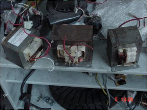
Rip em to bits..... and loose a few EE's and II's on the floor 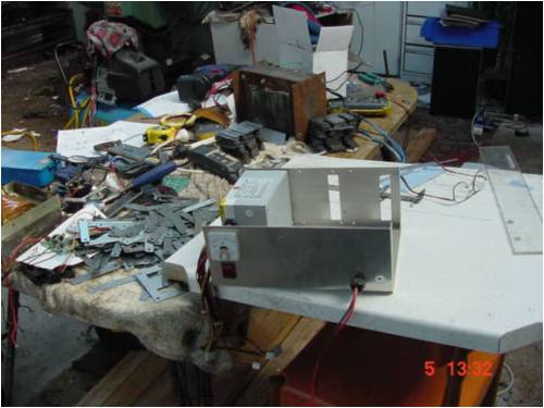
Work out your turns ratio and turns/volt using rule of thumb and wind coil (the chuck is over 250mm) for size comparison, 2mm wire: 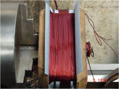
and build a box for it from the microwave oven, and we get a massive transformer that put out 40v@30A with a magnetising current of only about 1.5A.... all for free (the transformer is about 7-8 inches long .. can't remember exactly now. But it drives a variable speed 1hp dc pump at the local winery on the bottling line.... (slurp slurp) . 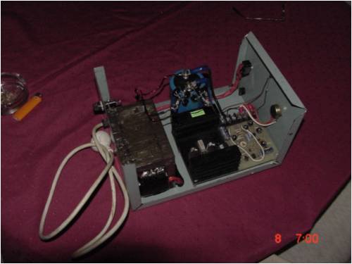
So the backyard theory works well enough to get what we need here, and can be used to wind the F&P transformers as well... just use appropriate cross sectional area for turns/volt.... there could be a table somewhere... but I've never found one sadly. So efficiency at any frequency can be the same, but the weight wont be, or if we use the same transformer at different frequencies, our efficiency will vary.. With a windmill..... like all things wind.... its a compromise. We are delivering low power at low frequency (cutin) so who cares about efficiency 0x0=0, if we design around the upper end of the spectrum we expect, we should do well. Thats why the AWP has a 350v transformer for 240v system... but a higher than you would expect secondary... use the leakage to your advantage. It develops max power at 240v... rms. The EMF will be around the 500v mark. It can give you some slip/elasticity so to speak, and let the TSR work a bit harder for you to negate some inefficiency. When working with wind, I've had to learn to think differently about how to implement the end game. It does not always make sense. The greatest example is using lossy resistance to improve the output into the batteries.... Or winding a low resistance stator, which cant work well (stall issues), so you can implement a long lossy feed and use the heat up there and improve TSR at the same time, and keep heat away from the stator etc lateral thinking perhaps. With the F@P, it seems to suffer current limit, so if we can let the voltage rise more, we can extract more power from the stator before current limit may cut in higher up the EMF scale etc...Caps look a whole lot simpler I guess. ............oztules Edit, I'm not sure if this is wholesale thread jacking, or helping the thrust of it?. If it is thread jacking, then feel free to delete this post Glen. Village idiot...or... just another hack out of his depth |
||||
| Dinges Senior Member Joined: 04/01/2008 Location: AlbaniaPosts: 510 |
[quote=oztules]and build a box for it from the microwave oven, and we get a massive transformer that put out 40v@30A with a magnetising current of only about 1.5A.... all for free[/quote] Peter is shocked to read that Oztules builds low-tech linear powersupplies in this day and age. That's, like, soooo 20th century! Couldn't help but think of this video as I was reading your reply: a poor-man's single-phase VFD, using a PC as audio generator to drive an audio amplifier. Output of the amp is transformed to ~120V and used to drive an induction motor. Poor 4-pole motor being run at 9000 RPM...  . Notice the toroidal power supply transformer being driven at 300Hz: . Notice the toroidal power supply transformer being driven at 300Hz:
http://nl.youtube.com/watch?v=6UbO1B5qtBk More on topic: if you want to transform 100W of 50Hz AC power, you use a 100W transformer. If your AC is 100Hz, you can use a smaller transformer. If your AC is 10Hz, you must use a larger transformer (one that would be rated for, say, 500W @ 50Hz?). And as Oztules said, the ONLY reason for 400Hz AC aboard aircraft is that it allows the use of much smaller and, more importantly, *lighter* transformers. I guess it all comes down to the point that transformers must be derated if you use them at lower frequencies than which they were originally designed for. If you want to use them at higher frequencies they could be 'uprated' as far as iron goes... but there may be other limits to the power that can be pushed through it, as e.g. wire thickness/max. current capacity. Off-topic: Oztules, when I built transformers I designed for current densities in the order of a (conservative) 3A/mm^2; more daring designers used 4A/mm^2. A few days ago I made some similar calculation for the 10hp motor, which pushed 9A of current through 0.65mm dia wire in its original configuration. That gives current densities of ~27A/mm^2... My jaw dropped. A lot. That's nearly 10 times the value I used in transformers. Was a decent German motor too, brand 'AEG', not some cheap Chinese junk. So I guess it's all perfectly fine, being designed by German engineers and all. But still... 27A/mm^2! 
Peter. |
||||
| Tinker Guru Joined: 07/11/2007 Location: AustraliaPosts: 1904 |
Thanks for that Peter. I wonder why the motor was run up in the next room  Perhaps he thought like me, I was watching the video, sitting sideways from my screen and ready to duck as the motor revved up, just in case one of the fan blades decided to go walkabout Perhaps he thought like me, I was watching the video, sitting sideways from my screen and ready to duck as the motor revved up, just in case one of the fan blades decided to go walkabout  Klaus |
||||
| Dinges Senior Member Joined: 04/01/2008 Location: AlbaniaPosts: 510 |
This what you are looking for? WPV = 45/Ay with WPV=windings per volt Ay=sectional area (in cm^2). 
I've scanned the entire article but I doubt it's of much use as it's in Dutch. It's a very good article nonetheless. Translation of the most relevant part from the first page ( http://picasaweb.google.com/motorconversion/TransformerDesig n#5273717079547522434): "First we determine the amount of turns per volt (WPV). This only depends on the iron cross section: WPV=45/Ay. Per 1 volt EMF of a coil you must use this number of turns, that is, so many revolutions around the core. The larger the transformer core the lower the WPV will be. For a slightly sizeable transformer it will be less than 10. The number '45' is an empirical value which is valid for old-fashioned transformer iron. Nowadays there exists better material, for example in C-cores. You can use the number '30' for that. But it's hard to tell [what iron material you're dealing with; PD]. For 'stacked tin' [literal translation; PD] it's best to simply use the value of 45." If you're feeling up to it... here are the full scans of the Dutch article... first page one is dealing mostly with WPV and sizing of cores, with some more details (also on saturation and loss) on page 5: http://picasaweb.google.com/motorconversion/TransformerDesig n# Hope this is of use. And with some more apologies to Readyakira for continuing the hijack...
Peter. |
||||
| oztules Guru Joined: 26/07/2007 Location: AustraliaPosts: 1686 |
Dinges, I'm running close to the wind with this months usage, so I will skip the links till the new month cycle... and keep the bandwidth for just here and fieldlines till then. Could you give a small table of 50, 60,100 and 200hz cross section area for 1 turn/volt from your dutch paper. Your reply didn't mention hz. This may help budding designers of these devices... and correct me if my rule of thumb is too wayward. Re motor/transformer densities.... yes practice does not always mirror proper theory.... my ratty experiments probably are a good example. And NO.... not linear exactly.... PWM using a unijunction for the oscillator, some lm358's for the error amps and some hefty 50A 160v darlingtons for the output switching. Frequency is only about 2.5khz. Good for about 50A perhaps... but happy at 1kw all day. Currently used continuously at about 80% duty cycle, for 8hr shifts. runs just over warm for the day. .........oztules Village idiot...or... just another hack out of his depth |
||||
| Dinges Senior Member Joined: 04/01/2008 Location: AlbaniaPosts: 510 |
Oztules, The article I quoted from/linked to only deals with 50 hz transformers. I'm pretty sure that any semi-decent book on designing and building valve audio output transformers has the figures and equations you are looking for... Hm. Well what do you know...even wikipedia has that information, it seems; impressive: http://en.wikipedia.org/wiki/Transformer_design Notice the first equation under the heading 'equations'? E=4.44*f*N*A*B*10^-8 With E=EMF; f=frequency; N=turns; A=cross sectional area; B=flux density. The fudge-factor 4.44 seems to be 2*pi/sqrt(2). Rearranging for volts per turn we get: E/N=4.44 *f*A*B*10^-8 turns per volt (the inverse of volts per turn): N/E=10^8/(4.44*f*A*B) Looks like turns per volt has a direct linear relationship with frequency, as far as I can see. The same should apply for motors/conversions, I think: double RPM (speed) and you only need half the turns for the same output voltage. If I've missed something, I'll no doubt be corrected. 
Peter. |
||||
| oztules Guru Joined: 26/07/2007 Location: AustraliaPosts: 1686 |
Dinges, From your Dutch data, it would appear that I run a bit skinny with the steel, so there must be a lot of flexability in this stuff...(coz 5 works just fine) It seems closer to 7 in theory than to the 5 or more sq ins that I arrived at empirically. Thanks for that .........oztules Village idiot...or... just another hack out of his depth |
||||
KarlJ Guru Joined: 19/05/2008 Location: AustraliaPosts: 1178 |
I thought the really short answer to this original question was yes, the further you can keep the A/C the better. ie run the A/C down the tower and through the ground, at whatever you have wound you F&P to suit 12/24/48 and rectify it as close as possible to the load. simple advantage here is most conductors have three cores and A/C motor output is three phases thus run three wires for the price of two and gaining an equivalent 1/3 less resistance in the wire. as there are now three instead of two. As for the rest of this post, you guys are pretty cluey when it comes to this so I wont disagree with anything previously stated however way too complicated to understand for a simple aircraft engineer like myself! How about using the 7 phase system, running plenty of big cable back to a batteryless system like the windyboy that will take 200-500V and pump straight into the grid? the windyboy may be a couple of grand but solves lots of problems by the appearance of things here! Luck favours the well prepared |
||||
| Dinges Senior Member Joined: 04/01/2008 Location: AlbaniaPosts: 510 |
[quote=oztules]From your Dutch data, it would appear that I run a bit skinny with the steel, so there must be a lot of flexability in this stuff...(coz 5 works just fine) It seems closer to 7 in theory than to the 5 or more sq ins that I arrived at empirically.[/quote] I've always suspected the design guide-rules in that Dutch article were on the conservative side. But conservative is good. Notice that in the wikipedia article, under 'simpler formulae', they have 2 more equations: for 60Hz AC and flux density of 1.2T: T=4.85/a (T=turns per volt; A=sq.inch) Which seems to be identical to your empirical value of '5'. For 50Hz AC and flux density of 1.2T: T=5.82/a (which is somewhat between 'your' value of 5 and 'my' value of 7) These are just rules or thumb, not laws of the Medes and Persians, but I find it conforms pretty well to your rule/experience and the values in my article (notice though that that information is dated at 1964, even though the article itself is from 1994... I suppose some progress has been made in the past 40 years in metallurgy of transformer iron... )
What I also found very interesting in that wikipedia link was the table with iron losses for various transformer iron materials (M-4...M-50). With the difference in loss-per-pound being a factor 3 for 'cheap' (M-43) vs. 'normal' (M-15) iron. That's a huge difference in iron loss, and may be an important issue when deciding on whether a motor is suitable for conversion to a windgenerator. Somehow I suspect that the 10hp German AEG will score a lot better on iron loss than the 500W 'blue boy' conversion, which was basically a cheap consumer-grade Chinese motor. I did already notice that iron loss of the 10hp was smaller than I expected when I first rotated the shaft. Maybe this is because my expectation was based on experience with the (lousy) 500W Chinese motor with its (probably) lossy core? Flux has often mentioned the difference in performance of core material, but it was only after looking at that table I noticed the huge difference in performance (esp. w.r.t. loss). A factor 3... that would be something to take into account for future conversions; perhaps only use 'high efficiency' motors in the future as they contain higher grade core material ? Unfortunately I haven't been able so far to found out the exact core composition of the 10hp motor; I suspect something like M-19, which is advised to be used at a maximum of 1.2-1.3T; I'm slightly above that in the 10hp, at about 1.6T in nearly the entire tooth ( http://picasaweb.google.com/motorconversion/75KWMotorConvers ionBlueMonster#5207088829052819634 ) Now, if that 10hp motor in reality contains M-36 which is advised to be used at maximum 1T...
I did manage to find the original datasheet of the motor which has a *lot* of information, unfortunately nothing on core material.  I may try mailing AEG for that information. I may try mailing AEG for that information.
Back on topic to Readyakira's original question: both DC and AC can be used to transmit power at high voltage. The key here is 'high voltage' for low losses; whether we use AC or DC is of secondary importance, more a practical issue. It's just that AC is more convenient for amateurs like us, as it's relatively easy to transform with simple, old, reliable technology (transformers). But also notice that some high-voltage distribution lines in the powergrid are actually DC (google 'HVDC'). With modern technology (semiconductors, SMPS) it has become nearly as easy to 'transform' DC nowadays as it was in the past with AC. Peter. |
||||
| oztules Guru Joined: 26/07/2007 Location: AustraliaPosts: 1686 |
Memories of blueboy... Re: frequency figures? Did you mean 60hz=4.85, and 50hz=5.82?
......oztules Edit, I still think saturation is better than no saturation in your application... if you get 2t you should be even happier Village idiot...or... just another hack out of his depth |
||||
| Dinges Senior Member Joined: 04/01/2008 Location: AlbaniaPosts: 510 |
Yes, the 4.85 and 5.82 are values for different AC frequencies when designing transformers. After all, turns per volt depends on frequency too. Not sure why you mention the 500W conversion 'blue boy' here. They're not related to this issue of turns per volt. I mentioned that conversion because of core losses in the cheap motor and I'm curious as to how it will compare to the 10hp generator of (supposed) better quality. Definitely check out that wikipedia article next monday when you are free again to roam the internet... 
Peter. Edit: yes, we've had that discussion about saturation before. But there's still some nagging doubt in the back of my mind. Losses schmosses... |
||||
| oztules Guru Joined: 26/07/2007 Location: AustraliaPosts: 1686 |
These made no sense to me and appeared to be calculated wrongly. I had expected the turns of 50hz to be more than 60hz.. not the other way around.... Then I remembered the blueboy windings suffered a turns per volt deficiency in their first iteration too (albeit for different reasons)... and some antipodeons are just plain wicked 
Forgive me, I'll try to behave. ............oztules Village idiot...or... just another hack out of his depth |
||||
| Dinges Senior Member Joined: 04/01/2008 Location: AlbaniaPosts: 510 |
[quote=Oztules]These made no sense to me and appeared to be calculated wrongly. I had expected the turns of 50hz to be more than 60hz.. not the other way around...[/quote] You're obviously more alert than I was... my mistake, erroneously mixed both up. Has been corrected now in the original post. Peter. |
||||
| The Back Shed's forum code is written, and hosted, in Australia. | © JAQ Software 2026 |
