
|
|
Forum Index : Windmills : Some thoughts on forces that destroy HAWT
| Author | Message | ||||
| KiwiJohn Guru Joined: 01/12/2005 Location: New ZealandPosts: 691 |
Some thoughts on non-rigid turbines and the forces that destroy a HAWT. (These are my thoughts on the subject and I welcome reasoned discussion on them) Perhaps the most common format for the horizontal axis wind turbine is 3 blades which in the smaller sizes, which naturally includes most home built systems, the blades are rigidly afixed to a hub. The turbine blades and hub are subject to gyscopic forces which can be suprisingly strong and varying from moment to moment. To get an idea of these forces it is necessary to understand what forces are going to be acting on the turbines blades. To do this requires a basic understanding of gyscopic principles and there is plenty on the subject to read on-line, however for this particular situation (i.e. a HAWT) imagine that you are standing in front of and looking towards a wind turbine which is aligned for a wind coming from the North, which is behind you as you face south. Imagine the blades are turning in a clockwise direction as viewed by you. The tips of the blades on your left side are going up, on your right they are going down, at the top of the circle the tips are moving towards your right hand side which is in a westerly direction and at the bottom of the circle they are moving towards the east. If you consider the forces and inertia etc at each of those four points they are equal and balanced. If the wind changes direction the mill will yaw to face the new direction but when the mill starts to yaw those forces in the rotor disc are unbalanced. The sides of the circle are still moving up and down but instead of the top moving East and the bottom West they are being forced into another direction. The energy has to go somewhere and what happens is the turbine blades attempt to regain equilibrium by redistributing the forces, depending on the direction of the yaw part of the energy from the east/west is added or subtracted from the up/down vectors the result being the mill will tend to either 'rear up' or 'nose down'. Most builders dont want this to happen and so they build strong enough to prevent the mill tilting up or down. Now just because the mill cant tilt it does not mean the energy has been magically done away with but instead is dissapated in such undesirable mischief as trying to bend the blades forward or back and reversing this force twice per revolution. The same forces are also trying to break the hub away from the shaft. To build a mill strong enough to resist these forces requires blades, hub, shafts, bearings and tower to be stronger than they would otherwise need to be. Not only is it necessary to build strong to resist these forces but fighting them also slows the yaw rate, which gives a clue that the force that actually breaks the blades comes from the tail! Precis: My theory says that when the mill is yawed blades are bent back and forward with considerable force and this reverses twice per revolution. Obviously this could be bad news for any blade mounting system especially one that incorporates fatigue susceptible materials (aluminium?). So, what can be done about this state of affairs? 1.Lighter blades will reduce the forces but they have to be strong enough. 2. Reduce the yaw rate, hmmmm, maybe a longer tail boom would do that? 3. Reduce the yaw force, would a shorter tail boom or smaller tail fin do that? I think this would be impractical to do without getting a condition where the mill would swing to down wind and generally get quite confused. 4. Dont yaw with every little change of wind direction, this is what the big boys do with their power yaw systems. However anything that reduces yaw by locking the mill to the mast has the potential to torque (i.e. twist) the mast which might be embarassing if screwed coupled mast sections have been used! How about accommodating the forces somehow? There appears to be two ways at least of doing this and these are flexible blades and flexible blade mountings. This is pretty much how simple helicopters and gyrocopters tackle the challenges of gyroscopic related forces in their rotors, the blades are not rigidly fixed to the hub but instead are allowed to move up and down (a little) and also 'backwards and forwards'. They use, depending on the design, complicated hinges, flexible bushes or just flexible blades. For a windmill turbine we could choose from their examples and at least accommodate some of the forces that a turbine would face in strong blustering conditions. After much chewing on the end of my pencil I suggest the following: 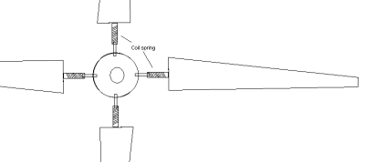
Each blade is attached to the hub via a short length of a rather stiff coiled spring, hopefully at least some of the forces that try to bend the blade or break the mounting will be accommodated by the spring. 
And a long tail boom too! (Sorry about the four blades but drawing three would be a challenge with PC Paint!  ) )
Well, those are my ideas for what they may be worth! 
(Now I need to go through this site and learn more about the favoured furling system as anything that allows movement of the tail relative to the axis of the mill would appear to be another avenue to reducing the blade breaking forces.) |
||||
oztules Guru Joined: 26/07/2007 Location: AustraliaPosts: 1686 |
John, As you will be aware, my mill is at ground level still, while I learn as much as I possibly can about how it behaves, and what to change. I have taken particular notice of the tail and yaw system. The yaw system (Piggot style) is very soft on the blade hub. It is able to turn the mill only by the gravity/angle vectors, and so is very very soft on the yaw head. To complicate matters for the tail, when the blades are working well, not much air seems to come out the back of the blades... ie the tail is shielded from most of the wind by the solidity of the blades. You can stand behind them in a blow, and light a match no problems.... one of the advantages of lots of wind at ground level, you can test things like this. So I would loose little sleep in protecting the mill from the violent shifts of the tail, because it just does not happen. The violent yawing seems to come from the offset and the blades themselves. As the gusts change their vectors... and quite quickly too, the pressure on the "blade disk" changes vectors.. very rapidly, and the mill head responds my yawing rapidly to match the new driving force vectors. I have taken the tail vane off, and held a short rope on the tail boom, (no airfoil now ), the wild yawing in the twisting gusts is exactly as when the tail was on the machine.... the blades do the sudden movement, the tail couldn't if it wanted too, the tail hinge would allow the tail to swing, but it would not "yank" the head anywhere, only use the angle vector to try to pull the head around... quite gently in fact. So... the tail swings, and basically asks politely for the yaw head to follow... which if it feels like it, it will, The wind direction dictates if it will shift, and the tail gives a bias as to where it would like the head to go. It can do no more. Being on an effectively free hinge, it can't tell it where to go with any force that would overcome the inertia of the head with any shock at all. As mentioned, the tail is out of the real wind by a large degree, and this softens it's response as well... The sharp corrections are driven by the head itself, not the tail.... when using the Piggott furling system.... at least that's what mine does. It may also be that as the blades approach solidity, they act as a flat disc.. front on to the wind, and this disk tries to stay balanced. It would explain the sharp shifts in a direction opposite to the yaw offset. This effect is like placing your hand out the window of the car at speed and changing the aspect of your hand to the wind. Flat on to the wind it is a solid steady push, but small movements off the wind gives violent up/down movement as the effective attack angle goes off center. It is this I think that gives the violent movement, and comes from the blade tip area to the hub, rather than the hub up to the tip. Tips the game on it's head sort off. ...........oztules Village idiot...or... just another hack out of his depth |
||||
| KiwiJohn Guru Joined: 01/12/2005 Location: New ZealandPosts: 691 |
Oztules, very good cerebral exercise material there! 
So if the sudden changes in direction (of rotor axis), which I still believe result in a bending force on the blades, is caused by the turbine disc itself rather than the tail that does seem to make a closer study of ways to relieve the blades all the more interesting. |
||||
| oztules Guru Joined: 26/07/2007 Location: AustraliaPosts: 1686 |
Yes I thought the tail dictated everything, but when you think about it it can only produce so much force on the yaw tube... depending on it's weight and angle, it is really a swinging hinge with bias. The 4m prop at speed must take real some force to turn it quickly, and a swinging hinge can't do it. It will certainly pull it around slowly (or try to) but the force to do it quickly is just way out of it's range, and if the wind is strong, the offset will just do it's thing, and the only alternative for the poor tail, is to go high up in the furl position. I guess this is proof, it can't dictate terms...or the furl wouldn't work. 
I haven't worked out figures for the tips, but at 2-300 mph in a 4m circle, they must have some serious G's operating on them, making them appear to be a lot heavier than they really are. So a strong blade is the only real answer I think. The first 1/3 of mine is silly strong, so won't be the first part to give up I reckon. ..........oztules Village idiot...or... just another hack out of his depth |
||||
| KiwiJohn Guru Joined: 01/12/2005 Location: New ZealandPosts: 691 |
No doubt strong blades are less likely to break, except that strong blades are heavier and hence the forces are greater and heavier blades mean stronger hubs, and stronger hubs are heavier...........and so it goes on. I am thinking that flexible is an alternative to strong... |
||||
| AllanS Regular Member Joined: 05/06/2006 Location: Posts: 67 |
You need something like an axial shock absorber that prevents the mill from yawing wildly. Is there any such thing out there? How about a long yaw tube filled with nice thick sticky grease with a flat paddle running up the middle? That would slow the yawing down. |
||||
Gill Senior Member Joined: 11/11/2006 Location: AustraliaPosts: 669 |
I recall a life time ago the CIAE (now CQU)did a study on house framing after cyclone Tracy. The thing of note was that wooden framing had some flexing and withstood storm forces better than rigid framing of a comparable strength. A tent or caravan annex secured by guy ropes withstands storms better when the guy rope has a spring device fitted allowing the rope some stretch to absorb the shock of gust loadings. You seem to have a good point. Perhaps "build strong" could be added to by "or build light with flex", but how and where do the benefits come in in a real life project? Helicopter rotors are awfully complex compared to the fixed ones we use now. Your coil spring method (or perhaps a Teflon rod would allow the desired lateral flex without stretch) makes for added engineering. Does the savings in material quantity or type warrant it? Still, good thinking, something to consider.  was working fine... til the smoke got out. Cheers Gill _Cairns, FNQ |
||||
| KiwiJohn Guru Joined: 01/12/2005 Location: New ZealandPosts: 691 |
Gill, the breakthrough in helicopter (gyrocopter specifically) design was discovered when Ciervo made a model with rotor 'spokes' of rattan. He was not looking for flexibility but the model flew better than his full size equivalents. The lessons learned apply no matter how complex or simple the rotor. Now I am not saying the coil springs are the entire answer but if they contribute anything they are certainly easier to incorporate than rebuilding the entire mill and tower. As a first step we could at least avoid materials that are subject to fatigue. Some helicopter rotors incorporate elastometric (sp?) bushes so maybe fixing the blades with rubber or suchlike bushes might be worthwhile? Suspension bushes perhaps? |
||||
| KiwiJohn Guru Joined: 01/12/2005 Location: New ZealandPosts: 691 |
AllanS, yes a yaw damper might be effective. You could use a surplus F&P with shorted coils?  You would have to be sure though that the torque could be easily handled by the mast/tower. You would have to be sure though that the torque could be easily handled by the mast/tower. |
||||
fillm Guru Joined: 10/02/2007 Location: AustraliaPosts: 730 |
My thoughts on the spring idea is the whole blade assy would become severly out of balance and be like a motor bike wheel with all the spokes loosened , on the fabrication side the spring would have to be specially wound buy a spring works as welding bolts etc to spring steel calcifies at the weld making it brittle , having a spring maker custom make a trial set would be extreamly costly . With regards to the yaw dampening I can see the merit in slowing the mills movement as a lot of power is lost as the blades react to a slight wind shift , I designed a yaw bearing assy that I was going to incorperate in #2 Quad that has a enclosed chamber filled with liquid silicon ( as used in car fan clutches ) with different quanities of fluid dampening can be increased and decreased . The use of grease is usless as a dampening agent it has no viscosity , extreamly heavy gear oil ( viserex 1200 ) could work , but silicon fluid is by far the best and cheapest , you can buy tubes of it at toyota .. ..PhillM .. PhillM ...Oz Wind Engineering..Wind Turbine Kits 500W - 5000W ~ F&P Dual Kits ~ GOE222Blades- Voltage Control Parts ------- Tower kits |
||||
| KiwiJohn Guru Joined: 01/12/2005 Location: New ZealandPosts: 691 |
[quote]My thoughts on the spring idea is the whole blade assy would become severly out of balance and be like a motor bike wheel with all the spokes loosened [/quote] Phill, having the blades flap around apparently does not throw a helicopter rotor out of balance. |
||||
| GWatPE Senior Member Joined: 01/09/2006 Location: AustraliaPosts: 2127 |
On my heli, only 2 blades, each blade has a pivot point on the end of each blade, that allows movement in the horizontal plane, to compensate for rotor torque. The only flexibility in the vertrical plane is the rigidity of the blade. The blades do pivot along the length and this is controlled by the swash plate. There is no flexibility that resembles what a spring would do, or a blade hinge mechanism like has been presented in ideas above. The heli blades are controlled in such a way to provide equal and opposite forces that balance on opposite sides of the rotor. The rotor disk integrity is maintained during flight. Individual blades cannot move independently in all dimensions. At very high rpm, centrifugal forces become dominant and thr rotor becomes stronger WRT the wind energy trying to move it. Gordon. become more energy aware |
||||
| KiwiJohn Guru Joined: 01/12/2005 Location: New ZealandPosts: 691 |
But not all helicopter blades are like that are they Gordon? Some are 'fully articulated'. |
||||
| oztules Guru Joined: 26/07/2007 Location: AustraliaPosts: 1686 |
Not everyone understands how the tail effects the yaw, and a lot have yet to build one. So further to what I was saying yesterday, here are some piks I took this morning of the furling at work. It shows that the yaw tube is taking no notice of the tail boom at this time, and now is when the gusts are the most damaging. Further, watching it, they move in the opposite directions in these winds, the offset pushes the head back around the pole in a gust, while the tail gets sent upwards in the opposite direction. 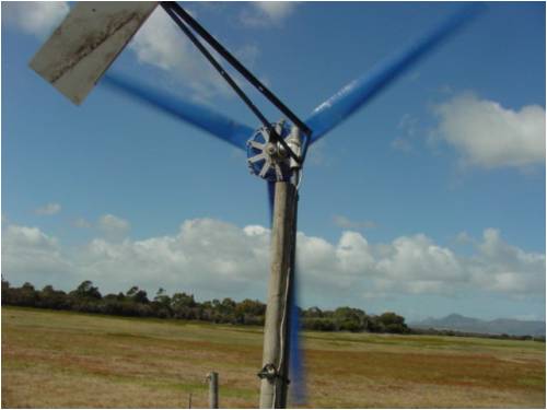
Here we are getting pushed towards furled, the tail has no hope of jarring the yaw tube, it can only exert a force moment on it... which is clearly insufficient at this time. 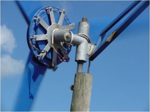
And here the tail has even less say on proceedings. 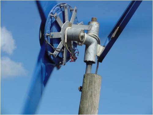
If you look closly at the second picture, you will see a slit in the triangular shape that dictates the angel for the tail. This is used in conjunction with a big shifter to bend it left to right to get different force moments on the yaw tube to set furl.... grubby but works. When I'm happy with it I'll weld it up. One other thing that is odd, this pole is only about 2/3 of a meter into the sand, no guys, and pulls many kilowatts at times (seen up to 5), and it hasn't fallen over yet.... and doesn't shake.(I can push it and it moves) I had expected disaster by now, but it hasn't happened ... yet. Maybe the gyro forces are not as severe as on the mast as first supposed. something to ponder.
.........oztules Village idiot...or... just another hack out of his depth |
||||
| KiwiJohn Guru Joined: 01/12/2005 Location: New ZealandPosts: 691 |
Well you have convinced me that the tail is innocent as far as forcing a yaw against gyrscopic effects!
I would still like to know what the incidence is of blades getting fatigued and broken through the effects of a sudden yaw (for whatever reason) being translated into a blade bending force. Otherwise, I think I have just about said my piece and that is that I believe there is a strong promise of advantages to be had from having an open mind towards flexible mounting of rotor blades. |
||||
| oztules Guru Joined: 26/07/2007 Location: AustraliaPosts: 1686 |
Hi John, I can only recall one instance on fieldlines and here, where wooden blades have failed because of no other factors than wind. Several have hit the tower and bust, but thats poor head design (few more degrees tilt would stop that). Several have collided with the tail (which was in the process of overfurling, or falling off from fatigue (AWP over here finished up the glass blades like that). Danb had his big blades self destruct, but it appears to be because they used short slivers of wood glued up to make the blade, and all the joins were in the same region... asking for trouble and getting it. Just the design of a wooden prop suggests that it just isn't going to happen, if it is carved as per Hugh or Danb. The strength is built into the design as is the flexibility where you need it. Wood is just an excellent material, and withstands these forces easily from the look of it. My ratty pine blades should self destruct, full of knots, and the poorest timber you could select (radiata pine), and it still wont break. I have seen huge rpm (probably near 800) when I foolishly let it loose from the batteries, and an instant stop (about 1 second) ...didn't bother them at all. Plastic and other more rigid materials are a different matter. I currently think the cure is worse than the disease for the wooden types. I would not consider any other material as a starter.... definitely including fiberglass. Thats my experience with it anyway. ..........oztules Village idiot...or... just another hack out of his depth |
||||
| The Back Shed's forum code is written, and hosted, in Australia. | © JAQ Software 2026 |
