
|
|
Forum Index : Windmills : trying to build 1st windmill
| Author | Message | ||||
CraziestOzzy Senior Member Joined: 11/07/2008 Location: AustraliaPosts: 152 |

Due to the crash of the webserver, lost previous reply and several questions from th OP as well...in reply to OP's progress of using magnets as they are with the current proposed setup, I decided to upload snapshot of the FEMM analysis I had previously not wanted to show. The magnets are doubled up in the simulation (two stacked together per magnet) and each magnet is alternating polarity to the adjacent magnet (N,S,N,S, etc.). I used materials as provided by the OP and also to the dimensions of scale proposed for the OP's setup...even the airgap is set 
I decided to make the cross-section using the outer periphery of the diameter ot the rotor as opposed to closer to the center where the magnets are closer together. I arranged the magnets with the curvature of their face pointing up towards the rotor where the coils are. I strongly do not recommend having the "U" orientation as those edges are very bad for the flux and cogging. There is little concentration of flux (the pink stuff shows highest values, decreasing in scale to yellow etc) where the coils are, with magnetic flux being lost inside the rotor. This was despite me having the coils on the rotor wound around the same material of the rotor ("iron"). I don't recommend using an iron filling mix as eddy currents went ballistic...not good. If you choose this way, have as much iron as opposed to epoxy as strength of the cast can allow. I also recommend further researching on magnet polarity arrangements from similar experiences of other DIY's using brake rotors setup for generator use. Pay particular attention to phase and whether you would be better off having a NN, SS arrangement etc.. I also suggest spacing the magnets closer together around the radius of the rotor as this had some good effects on concentrating flux closer to the coils rather than it getting lost inside the rotor. Cheers http://cr4.globalspec.com/member?u=25757 http://www.instructables.com/member/OzzyRoo/ |
||||
divemaster1963 Regular Member Joined: 28/01/2009 Location: United StatesPosts: 46 |
I have chaged coils and am now making 9 coils 21 gauge. 37o turns. they are big but I hope they will produce better results. should i still go with iron cores. these are the only magnets i could afford. so i have to go with them. should I use iorn fillings with the eposy to seal magnets in or just the epoxy?. how would this show on your femm program. my coputer wont support the program. the gap is going to be as close as possible. maybe 1/16 th should i maybe double up on the magnets with 2 layers of nn ss nn on each rotor. thanks for the help. glade were backup. I'd be lost with out the help. |
||||
| CraziestOzzy Senior Member Joined: 11/07/2008 Location: AustraliaPosts: 152 |
Epoxy only 
epoxy only forget it 
Epoxy mixed with IRON fillings 
Epoxy imprgnated with as much iron fillings as strength will allow is passable 
High quality laminated core 
Using high quality laminated core (butchered from transformers etc) will work 
The last picture using laminated core with the coils surrounding these coils will work...but the phase may be interesting and worth looking into. The laminates are placed in unconventional manner. As you are looking side onto your set up in cross section, the laminates are stacked on top of each other looking into the plane. The plane ends are left to right as opposed to being the normal "up-down" as you are looking at it from your monitor. Your setup making do with what you got is unconventional and the simulation (unconventional) shows my idea may work in concentrating flux inside the laminated cores which are surround by your copper coils. Normal setups I simulated concentrated flux inside the rotor...not good. I also shifted the "firing" position by moving the rotor to the right in the last pic...which is why your phase may be interesting. This shift (combined with the "innovative" orientation of the lamination) showed when the maximum flux occured around the cores rather than be lost inside the rotor. Ignore the right half of the pic (as too all the other pics, as the magnetic circuit is incomplete...the left half is a complete circuit). Notice only one half of the coil is "energised"...I think having N,N,S,S etc will work better and "energize" the coil on both "sides" but may require more RPM'S (as not all magnets will be "powering" the coils during one revolution), but that depends on how much current you want which of course is determined buy the gauge of the wire in your coils. As explained earlier, the polarity of the magnets in these simulations is N,S,N,S etc.. Note that when I shifted the rotor position as I did in the laminated sim for all the other sims, the effect of concentrating flux at the cores did not occur. Having the rotor offset in the last sim (for the purpose of showing position of maximum flux occurrence at the coils) plus laminated core will work in my mind. Although the strength of the flux will be slightly weaker but a fair compromise to get that flux in highest concentration at your coils where you want it. Doubling the magnets is a good idea...allowing more copper and increasing magnet "strength" http://cr4.globalspec.com/member?u=25757 http://www.instructables.com/member/OzzyRoo/ |
||||
| divemaster1963 Regular Member Joined: 28/01/2009 Location: United StatesPosts: 46 |
thanks for the sim. I go with duobling up the mags. 2 layers on each rotor. nn ss nn ss . I' use iron fillings wtih the epoxy around and cores in the stator. should I mix fillings when I incase the magnets or go with epoxy only. I' let you know how it turns out. and thanks for all your help
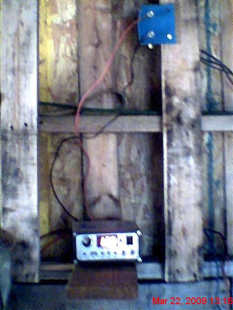
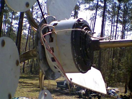
divemaster1963 Ps. i have been playing with a old regant fan. 36 slot with what looks to be 28 gauge wire. I'm only geting voltage from the red lead. I Know I got to rewind it. its just a litte project. hey tought you like to see what i have setup sofar in my shop  "> ">
two sets 1 six agms 2 5 acid deep cycle 
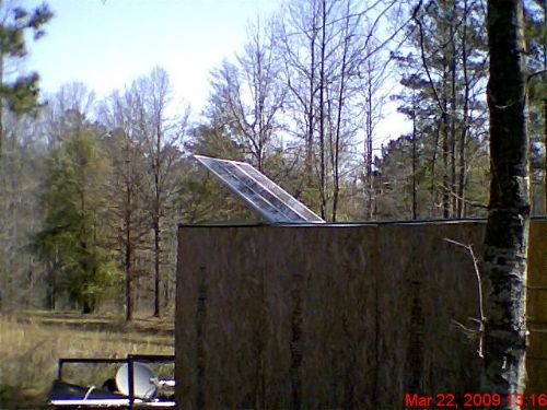
yea yea yea  It's a hp new style 45 watt 3 panel. It takes a few days of sun to bring the sets to full capcity. But in georgia we have a lot of sunny days. It's a hp new style 45 watt 3 panel. It takes a few days of sun to bring the sets to full capcity. But in georgia we have a lot of sunny days.

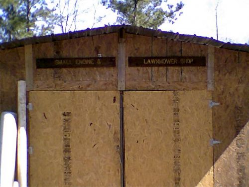
Oh by the way my shop is made from 4x4 pallets for the walls stacked 2 high and the floor is 3x16 pallets. got the idea from a man who has has for almost 15 years now and the termites don't miss withit. 
This is my little project mill 
|
||||
| divemaster1963 Regular Member Joined: 28/01/2009 Location: United StatesPosts: 46 |
sorry the first one did not post 
|
||||
| Gizmo Admin Group Joined: 05/06/2004 Location: AustraliaPosts: 5182 |
Repost of missing posts. These go above CraziestOzzy's post on the previous page, just to add little confusion into the mix. 
divemaster1963 wrote..... well I come to a decsion to scrape the 14 wire 36 turn. I now have found some 21 gauge deguasing wire. I'm goning with 375 turns with cores using my original mags doubled up n-s-n-s with should give me a 1/32 air gap. going 3 phase. I'll leave the connections out so i can reconfigure to get the best output. I also got my regant fan motor converted to pm. am going to wire it with full wave recs. parrell. jerry-rig. I got it putting out 36 volt ac hand turning no coging. wave a .010 gap 6 ferite mags. just a experiment for fun. I'll put photos of it up when i'm done. CraziestOzzy wrote..... Looking forward to see your creation. Just watch those amps...painful and nasty buggers Just curious to know if you are going to reshape those magnets you show earlier on. Cheers divemaster1963 wrote..... I was thinking of just leaving them in the small shape. I'm thinking of sealing the magnets to the rotors using epoxy withmetal filings. do you think this may work or willit hurt the magntic field? I'm kind at a stand still till I figure this part out. yea I know those amps bite. got hit at the landfill working on a doszer.  My arm still is stiff from the elbow down. My arm still is stiff from the elbow down.
CraziestOzzy wrote..... okay, here it is. The magnets I placed all in the same curvature towards where the coils are. I didn't like the alternating convex-concave arrangement. I assumed surrounding the copper coils were solid iron and NOT iron fillings etc. Iron fillings mixed with epoxy will make eddy currents galore and weaken flux strength in your rotor where your coils are. I could not get the flux to surround your coils, instead the good stuff got lost inside the iron in your rotor. That is where all that pink stuff is. The crests of your magnets (where the pointy raised edges are) will increase cogging dramatically if you do not machine them down or arrange the magnets the way I have in the simulation...I assumed you did not want to machine the magnets so after a few sims, This was the best arrangement, curved sides of magnets facing towards the rotor where the coils are. Cheers...and watch those amps Pics missing, but I think you reposted these on the last page. Glenn The best time to plant a tree was twenty years ago, the second best time is right now. JAQ |
||||
| divemaster1963 Regular Member Joined: 28/01/2009 Location: United StatesPosts: 46 |
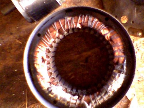
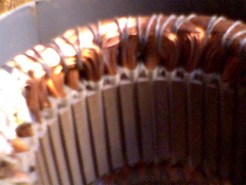
these are the missing photos 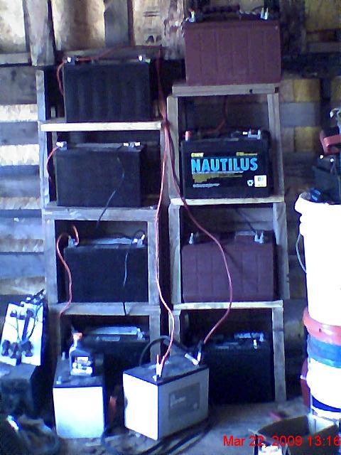
|
||||
| CraziestOzzy Senior Member Joined: 11/07/2008 Location: AustraliaPosts: 152 |
Mate, that fan motor is in need of an online strip show...bet half of us are drooling to see the insides
For serious energy, I would be using that fan motor and playing with your brake rotors as a time filling exercise  http://cr4.globalspec.com/member?u=25757 http://www.instructables.com/member/OzzyRoo/ |
||||
| divemaster1963 Regular Member Joined: 28/01/2009 Location: United StatesPosts: 46 |
will I'll get photos of it up this weekend. I put it in the shop because of rain. I have another motor from a ac outside unit that a friend gave me. here are some photos. I'm going to wait till I can afored some neos before attacking it. don't what to destroy it. 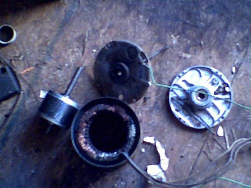
|
||||
| divemaster1963 Regular Member Joined: 28/01/2009 Location: United StatesPosts: 46 |
hey by the way found a masive tranformer. I have been cutting laminations off of it. I can fit 1/2 thick on ends so should be more like a motor style . hope it will work  |
||||
| divemaster1963 Regular Member Joined: 28/01/2009 Location: United StatesPosts: 46 |
Ok small update. I now have all 96 magnets for my rotors. 48 for each face. 12 groups of 4 mags. alternating nn ss nn on each rotor. 21 gauge wire 375 turns. laminated cores for coils. I'll be assb. the rotors this weekend if the honeydo list is do  . I have one question for CraziestOzzy. . I have one question for CraziestOzzy.
when you said that in the simm you off set the mags. what did you mean by this? we lost the posts. I want to make sure before I secure the mags to the rotors. did you mean: nn ss nn ss nn ss nn ss or did you mean: nn ss nn ss nn ss nn ss nn ss or did you mean: nn ss nn ss nn ss nn ss nn ss: sorry I just don't what to screaw this up. I would like to do a complete diary on this when I finish so that others who are just thinking about this can see you can do something with very very little money and a good bit of free time to make a genny functional.
I am going to show all have help me get the warm thanks you all deserve. |
||||
| divemaster1963 Regular Member Joined: 28/01/2009 Location: United StatesPosts: 46 |
the post did not show the offset I put in. let me try it this way. nn-ss-nn-ss-nn -ss-nn-ss-nn-ss |
||||
| The Back Shed's forum code is written, and hosted, in Australia. | © JAQ Software 2026 |
