
|
|
Forum Index : Windmills : Homegrown - Ax Fx -
| Author | Message | ||||
| KiwiJohn Guru Joined: 01/12/2005 Location: New ZealandPosts: 691 |
Nice job Phill! |
||||
oztules Guru Joined: 26/07/2007 Location: AustraliaPosts: 1686 |
Egad!! thats some serious engineering there. Well done. Answer to your question...... lots and lots... and then some....... 
........oztules Village idiot...or... just another hack out of his depth |
||||
| KiwiJohn Guru Joined: 01/12/2005 Location: New ZealandPosts: 691 |
Phill, I dont doubt you have done your sums and your design sure looks 'nicer' than most with the neat, uncrowded, disposition of your coils. Now that I have a lathe such a project might be within my grasp so I must ask is there any special requirements for the steel? For example does it have to be high Mu? |
||||
fillm Guru Joined: 10/02/2007 Location: AustraliaPosts: 730 |
John , I have not used any special steels , 10mm plate and 300nb x 12mm pipe , this design and the layout of the coils and magnets , I can not take credit for as Gordon has done the calcs on sizes / windings / etc and has guided me to this point , he is also making his at present ,but there are some differences in the bearing hub and blade mounts between the two. Hopefully I should have this up and flying within a month , I still have to get the furling spot on ,when I have the 2 mills up as they will easily exceed the capacity of my grid inverter when it starts to blow , but the best thing with this one is if it needs shuting down it will where as the F&P will saturate and go onto overspeed , which I have seen happen on a few ocasions and proved on the lathe tests . PhillM ...Oz Wind Engineering..Wind Turbine Kits 500W - 5000W ~ F&P Dual Kits ~ GOE222Blades- Voltage Control Parts ------- Tower kits |
||||
| GWatPE Senior Member Joined: 01/09/2006 Location: AustraliaPosts: 2127 |
Hi oztules, the magnets really take a hold at the really narrow magnet gaps. At the 12mm spacing, there is more significant pull than at 18mm, but only a fraction of the pull of the magnets at the 3mm gap as in my original AxFx machine. Nice job there Phill. You are way ahead in the time line to me. The stator came out really well. The 2 stage casting process certainly allows accurate placement of coils and terminations. The Utilux solder eyelets seem to work well. I will still use the flexible style as this works better with the slip ring assembly in the yaw box on my mill. I have a lot of holes to thread tap, and I am still winding coils. I still have to wait for the aluminium magnet alignment template to be cut. Hi KiwiJohn, the coils sizing and geometry, and the magnet spacing were empirically determined, with test coils and a precision adjustable magnet gap prototype rotor assembly. The number of turns of the particular guage winding wire was optimized to give the lowest winding resistance for the desired output voltage. The phase to phase resistanse is around an ohm for a 48V mill, so this will be OK. Gordon. become more energy aware |
||||
| KiwiJohn Guru Joined: 01/12/2005 Location: New ZealandPosts: 691 |
Thanks for the info, looks good and must be one of the neatest designs on the 'Net. |
||||
| Bazarghai Newbie Joined: 13/05/2009 Location: HungaryPosts: 1 |
Hi fillm! I've studied your windmills and stuffs you made. I really loved your attempts to make a multi-stator F&P windmill. I am building my second windmill(would be double-stator), and I'd like to make a conversation with you about wires, mechanics, blades. I didn't find ur email in the profile. So if you have a good mind to talk please contact me. bazarghai at gmail dot com PS: sorry for my poor english, i'm came from Hungary... B |
||||
MacGyver Guru Joined: 12/05/2009 Location: United StatesPosts: 1329 |
My hat is off to all you guys turning your own windings; nice work. In my early windmill-building days, it soon became apparent that changes in wind speed ran the frequency of electricity generated directly from the turbine all over the place. For that reason, I decided to use the electricity as a heat source for heating water. I simplified my design and spun the magnetic field instead of the windings. I carefully press-fit several strong magnets (no neo-mags in those days!) into a circular piece of plastic (similar to Delrin) so it was well balanced and attached it to the shaft of a shallow-pitched, upwind Stuart mill. Each consecutive magnet was pressed into a hole and oriented so the poles on one face of the disk were N-S-N, etc. As the turbine spun, the attached magnetic wheel spun through a soft- iron "C" shaped core wrapped with No. 10 copper wire. The core came from a used shaded-pole bathroom exhaust fan. I merely reshaped the pathway through the soft iron piece and re-wound the existing coil. I used the electricity created by the wind spinning it to heat water, since frequency didn't matter. I wish I had taken pictures, but it was a long, long time ago and I didn't. At any rate spinning the permanent magnets was a lot less bother than building an armature and creating a commutator with brushes, then spinning it. For those of you who have a lathe and arbor press, give it a whirl; it's a fairly-easy project. Oh, I forgot to mention one thing: I didn't come up with an easy way to transfer the power to the ground (brushes?), so I installed it in a fixed position facing the Gulf of Mexico where the wind direction changed very little all day long; each day. Nothing difficult is ever easy! Perhaps better stated in the words of Morgan Freeman, "Where there is no struggle, there is no progress!" Copeville, Texas |
||||
| GWatPE Senior Member Joined: 01/09/2006 Location: AustraliaPosts: 2127 |
Hi MacGyver, These machines are alternators, with a stator of wound coils with rotating permanent magnetic fields that through cut the coils. Gordon. become more energy aware |
||||
| fillm Guru Joined: 10/02/2007 Location: AustraliaPosts: 730 |
Hi All Finally got my finger out over the last 3 weeks to get the Ax-Fx finnished and up in the air , there was a lot of other work to complete before I could eventually get this finnished and flying as another tower / tail / blade hub /wiring etc etc all needed finishing and now I have two mills up in the air , the Ax-Fx ( now nic named " The AX") and the dual F&P and I will be opening another thread on" The AX - vs - F&P Dual " Working with these 2'' Neo magnets is an eye opener and keep your witts about you , while putting these into position on the rotors I passed to close to one of the rotors with a magnet in my hand and had it ripped out and slightly chipping an edge , luckily no finger damage this time , once there mag forse takes over theres nothing you can do to stop the collision and getting them apart is a task .. 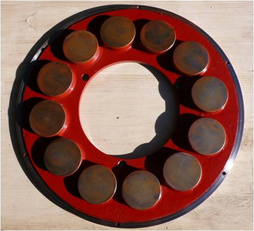
Rear Rotor 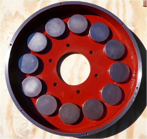
Front Rotor 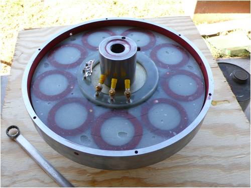
Stator in 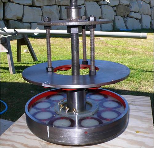
This is the assembely tool I made to deal with getting the two rotors together with out getting any hands and fingers in the road of 24 neo's pulling togther , at this point is where I can't turn the nut by hand 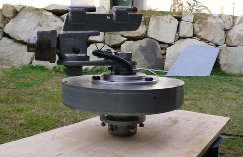
All assembled to the yaw bearing .. 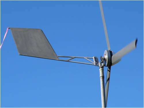
The moment that we all love , getting it in the air and seeing what the output is .. After all this I have to give credit to Gordon for the work and caculations he has done in this project and the help he has given along the way. The data from how this is performing will be put into a new thread as I think it is a whole new topic .. " The Ax - Vs - F&P Dual " PhillM ...Oz Wind Engineering..Wind Turbine Kits 500W - 5000W ~ F&P Dual Kits ~ GOE222Blades- Voltage Control Parts ------- Tower kits |
||||
| oztules Guru Joined: 26/07/2007 Location: AustraliaPosts: 1686 |
Beautiful work Phill. The envy is all over the place here. If you get the furling correct, this looks the ticket. I have just pulled mine down... cancer in the neo's from weather exposure. (were embedded in resin... now in epoxy paint.. with epoxy between the mags and the steel disk. I would recommend sealing them somehow. Look forward to results.. F&P should get a clobbering... but I've been wrong before too 
...........oztules Village idiot...or... just another hack out of his depth |
||||
| GWatPE Senior Member Joined: 01/09/2006 Location: AustraliaPosts: 2127 |
Hi Phill, All looking good. One difference with my new AxFx is that the magnet plates sit in a recessed step on the ring. I am looking forward to the comparison data. Gordon. become more energy aware |
||||
JimBo911 Senior Member Joined: 26/03/2009 Location: United StatesPosts: 262 |
Hello Phill As always exceptional work once again congrats. It will be interesting to see your production data. Question do you have any pictures of the blades mounted (fixed)to the hub since this is where I am at with my F&P. Jim Jim |
||||
| fillm Guru Joined: 10/02/2007 Location: AustraliaPosts: 730 |
Ozz ,I think you won't be wrong about the clobering , theres a change coming through today and it will be interesting to see how both go , unfortunatle I am at work 1000k away and will kept informed by the other half and hope nothing drastic goes wrong , but the dual piclog will record it all . But just the other night from 12am to 7 am we had a sneaky little breeze of 4-9klm and the Ax made 150W/hr where the F&P did 14W/h , but we also have to take into consideration that there is a massive cost and engineering difference between the two and one was origionally designed to wash cloths and the Ax is purpose built ,so I would expect the Ax to do better. I have also noticed that arround the 12 to 18 klm there is not much difference in output at about 100 to 150 Watts. Jim , I will be posting soon a blade hub and s/s tubes that I have designed for the PVC blades that will suit the dual stator mounting & housing / shaft and front rotor mod / yaw bearing assy kit I will be offering for sale , although it is probably not what you are thinking of, but you still might get some ideas from the pics.. PhillM ...Oz Wind Engineering..Wind Turbine Kits 500W - 5000W ~ F&P Dual Kits ~ GOE222Blades- Voltage Control Parts ------- Tower kits |
||||
| brucedownunder2 Guru Joined: 14/09/2005 Location: AustraliaPosts: 1548 |
Hi Phill ,, As allways, excellant workmanship .You are very skillful. we are expecting strong winds today,at present ,I'm seeing 30 plus Kph ,,so you must be similar. I must get over ,will call you first. Bruce Bushboy |
||||
| The Back Shed's forum code is written, and hosted, in Australia. | © JAQ Software 2026 |
