
|
|
Forum Index : Windmills : New F&P dual stator
| Author | Message | ||||
| PLUGGY Newbie Joined: 12/04/2009 Location: AustraliaPosts: 8 |
Have been reading the forum with great interest.I am Building a dual stator F&P turbine.I already have the 2 60s F&Ps set up mechanicily with a 3M dia Chinees blade set ,and was wondering if anyone can Please explain in simple terms the best way to set up the electricals to hook them into our exhisting system.Capactors, doublers?Ect. We already have our house and workshop on a stand alone 2KW 48v solar system with a PL60 controller with 5kw inverter.Hopeing to increase power supply for cloudy days as we seem to be getting more cloudy the Last few years. Global Warming? Thanks and regards . |
||||
Bernie the Bolt Regular Member Joined: 26/10/2006 Location: United KingdomPosts: 45 |
Hi Pluggy, I am no expert but here is a link : http://lifeattheendoftheroad.wordpress.com/2008/01/09/wind-t urbine-wiring-diagram/ I suggest wiring your genny (after rectifying) direct to the pos neg bus bars in your system. That way it will always have a load connected. You may want to look at a dump load to prevent overcharging. (Imagine a good sunny day, followed by high winds at night, you would be asleep and presumably not much load on the system, what happens to all that surplus power the wind genny is making ?) Bernie the Bolt I'd rather be sailing! |
||||
| PLUGGY Newbie Joined: 12/04/2009 Location: AustraliaPosts: 8 |
Thanks for the link Bernie,unfortunatly this doesent help me with the f&p system. |
||||
| GWatPE Senior Member Joined: 01/09/2006 Location: AustraliaPosts: 2127 |
Hi Pluggy, If the info given so far does not help, you may need to seek assistance from a person. The F&P is still just a 3phase Alternator and will require rectifiers and a voltage controlled diversion load. There may be some regulation conflicts with the solar system as well. I would let the biggest system control the battery maintenance. It seems best in your case for the windmill output to be diverted to a heater bank if the battery is above float voltage. This will prevent overcharging, especially if you have gel type battery. Not as critical with flooded systems. Diode isolated systems will be required to stop the diversion from activating with the solar. This is easily done with positioning of the windmill battery sense voltage location. on the windmill side of the windmill blocking diode. It is a bit of a learning curve, so do not be discouraged. Gordon. become more energy aware |
||||
fillm Guru Joined: 10/02/2007 Location: AustraliaPosts: 730 |
Hi Puggy, May be the simplest solution which is not the most economicial is to use a PL20 to controll the mill and dump load and then you will have to adjust the solar reg voltage and wind voltage on program 4 , either have the solar or wind reg voltage set above the other .. With your dual , you would be better off trying to get a couple of 80s stators , configure them as 2s7p , twist the poles to minimise clogging , Then set up two voltage doublers / cap coupled and you will have a mill that will perform in all winds and max out upwards of 800w , which mine is doing in 35 to 40 klm and still making power 10 - 30w in 6 to 9 klm I have been running 48v , but into a grid connect system , and hav trialed many different combinations , and this is buy far the "WINNER" , a 60s will not work well with caps ... If you need a dual bearing housing to get it all started I have a few kicking arround from my quad stator... PhillM ...Oz Wind Engineering..Wind Turbine Kits 500W - 5000W ~ F&P Dual Kits ~ GOE222Blades- Voltage Control Parts ------- Tower kits |
||||
| PLUGGY Newbie Joined: 12/04/2009 Location: AustraliaPosts: 8 |
Thanks Gordon and Phill for your help so far.Have been following your projects for a while Phill.Sounds like your latest mill is working well.I presume this is one you refere to in your reply to me.I was actually planning and prepared to make a copy of your 4 rotor beast ,but decided to follow the later 2 rotor plan with capactors.Just Have a few questions about how to set it up.I have heaps 60 series setups dumped from our local whitegoods suppliers but no 80 ser.I already have the 2 60 ser set up and have twisted the poles .How important is the difference between the 60s&80s for this project? Can I use my Plasm PL60 to control both solar and wind at the same time? Do i need to convert my stator to 7p? is this for cogging only? Have been following Forum on capacitors wondering what capacity You settled for in the end Phill.Is the wiring setup for your mill as posted good, also wiring dia I think Gordon made good?Also wondering what the voltage doublers are and where to get them? Our Exhisting system has 24 x 2v 1350ah exide wet cells. |
||||
| fillm Guru Joined: 10/02/2007 Location: AustraliaPosts: 730 |
hi Pluggy , First off , do you have a good wind ? I use two controllers 1 pl60 for the wind and a pl20 for the 4 x 80w panels , I dont think tou can use the one controller , contact plasmatronics and ask them . The 60s have to high of a resistance for running caps I was told , even the 80s failed in the unmodified stator test , but when configured to 7s2p worked well.. Use 60s unmodified in delta and you should get 400w in good wind .. Voltage doublers are made not bought , using 35a bridge rectifiers , the wiring dia is posted in "Testing Capacitors" P5 , cap size is quite open 100Uf to 350Uf but the voltage needs to be 350V + . Do you have some pics of your mill? PhillM ...Oz Wind Engineering..Wind Turbine Kits 500W - 5000W ~ F&P Dual Kits ~ GOE222Blades- Voltage Control Parts ------- Tower kits |
||||
| PLUGGY Newbie Joined: 12/04/2009 Location: AustraliaPosts: 8 |
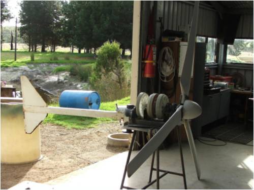
some photos of progress so far. 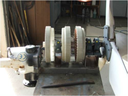
|
||||
| PLUGGY Newbie Joined: 12/04/2009 Location: AustraliaPosts: 8 |
|
||||
| PLUGGY Newbie Joined: 12/04/2009 Location: AustraliaPosts: 8 |
Hi All Phill ? I think I will start off with the 2 60s untill I locate some 80s.Can i hook 1 in star other in delta? Where can I locate a dia how to do this? RGDS Carl |
||||
DaViD Senior Member Joined: 14/01/2009 Location: United StatesPosts: 120 |
Thats a good looking machine you have there PLUGGY can you come build mine for me?   If your not living on the edge your taking up to much space! |
||||
| GWatPE Senior Member Joined: 01/09/2006 Location: AustraliaPosts: 2127 |
Hi Pluggy, the mill looks like a chop/shop job on a chinese type mill. How far ahead of the tower pivot is the blade rotor? Looks quite a way, and this will change the furling. Gordon. become more energy aware |
||||
| PLUGGY Newbie Joined: 12/04/2009 Location: AustraliaPosts: 8 |
the mill looks like a chop/shop job on a chinese type mill. How far ahead of the tower pivot is the blade rotor? Looks quite a way, and this will change the furling Hi all The mill is an Modified chinese that dident work properly (49v in a cyclone).So chopped it up for this project. As you say the furling has probly changed as hub is approx 200mm further forward.I suppose there is no way to test this on the ground.Trial and error when flying? I am making the tail larger as the original is to small ,so this will also have some effect? The question is How big does the tail need to be?. Still lots of things to work out.Main thing still to work out is the wiring of the stators. in the pic the end spare rotor is a stripped out hub which i plan to make into a manual brake. Rgds Carl |
||||
| GWatPE Senior Member Joined: 01/09/2006 Location: AustraliaPosts: 2127 |
The system voltage is at 48V. Was the chinese mill only 24V, or sounds like 12V. You would not even get to battery cutin. What power level rating was the original mill? What system voltage was the original mill designed? A voltage doubler/tripler, of suitable capacitor sizing may have been all that was required to make the original mill work for you. Does the original mill have slip rings? I have found sources of cheap caps on the net. I just purchased some. The power in a tripler is distributed between many caps, so ripple current ratings are not as critical as the series cap arrangements. Can you fill in some of the blanks? Gordon. become more energy aware |
||||
| PLUGGY Newbie Joined: 12/04/2009 Location: AustraliaPosts: 8 |
Hi Gordon The original chinese mill (Ebay) was supposed to be for a 48v system 1000w@48v had a crap controler with it which I modified to get it to work.Gen was quite solid and well made but had it going for a while and the highest i ever saw out of it (very briefly) Im a howling gale was 49v AC before the controler no load.we tried to rewire it star & delta also rewind stator but gave up.to hard .This was about 2yr ago. If i new what I know now we would done more. BUT you see the shaft in the pics,that is the original rotor shaft so as you can see there is no turning back Unfortunately. The original mill rotor was a brushless 6 neo magnet rotor .Has 3 slip rings on the yaw pivot. Regds Carl |
||||
| GWatPE Senior Member Joined: 01/09/2006 Location: AustraliaPosts: 2127 |
The low output could be from overheating. The units usually produce the rated voltage. 49VAC gives over 68V peak DCV. Would probably have been a good candidate for a voltage doubler. No way back now. The long distance of the blades from the original length will still need to be adressed in the furling. Will probably furl too early if mill head geometry is not changed. Gordon. become more energy aware |
||||
| The Back Shed's forum code is written, and hosted, in Australia. | © JAQ Software 2026 |
