| Author |
Message |
readyakira

Senior Member

Joined: 17/07/2008
Location: United StatesPosts: 114 |
| Posted: 07:39pm 21 Jul 2009 |
 Copy link to clipboard Copy link to clipboard |
 Print this post |
|
Here are some pics I took for you all to use as reference. I will edit this more later just want to get the pics up while I am at a computer...
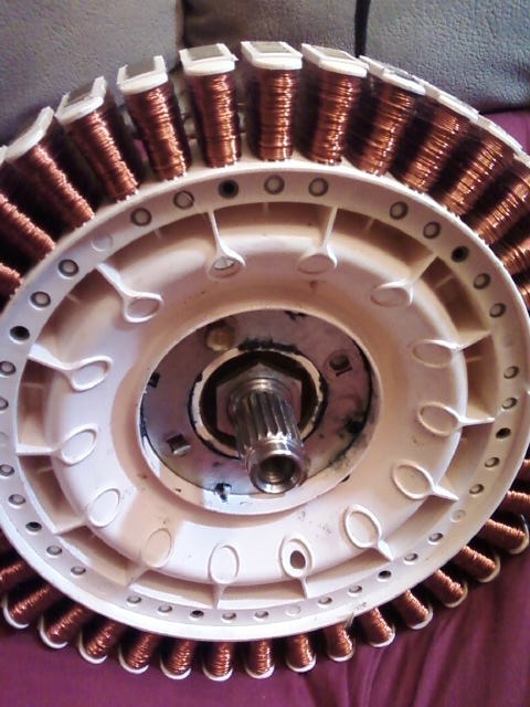
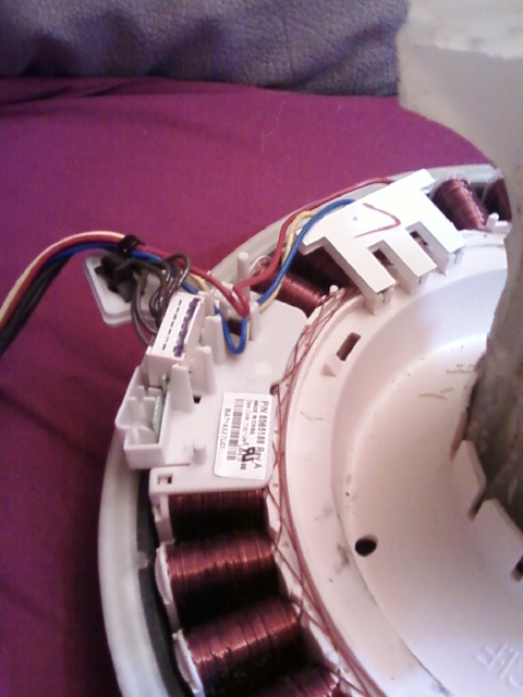
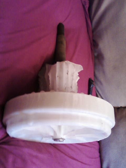
This first on shows a F&P coil pack attached using the stock housing, bearings, and shaft out of a F&P washer. Notice the steel ring in the middle. You should keep both of these (one on each side) because they make lining up and centering much easer. Plus they give some added strength to the mounting surfae.
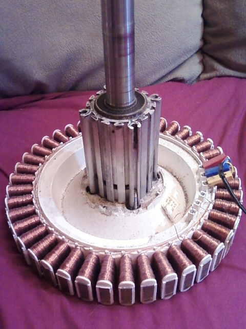
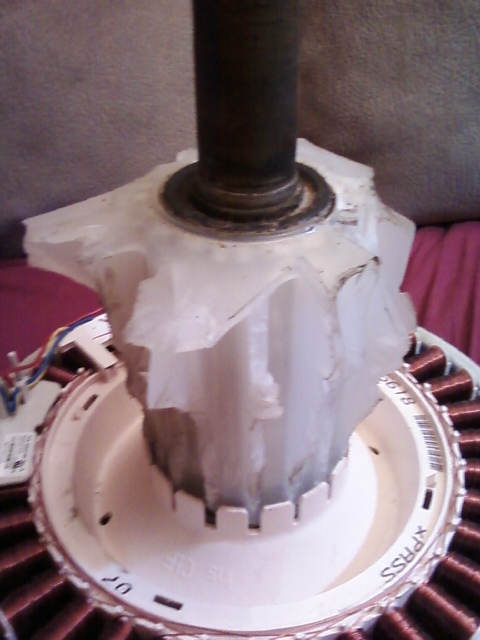
This pic shows more of the coils on the F&P but, mostly gives a good shot of the alluminum housing I kept from the washer tub. I cut this from the tub with a sawzall and then removed the bearings and melted the plastic off. You can see the center of the hub has had the tabs broken off. I did this to play with the idea of off setting this coil pack with another one on the other side of the shaft.
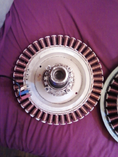
This one show a top down view of the same. You can see an Oasis assembly next to it. One thing I notced, the Oasis has much much less cogging then the F&P even as a stock unit.
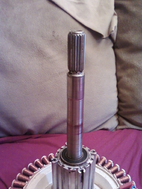
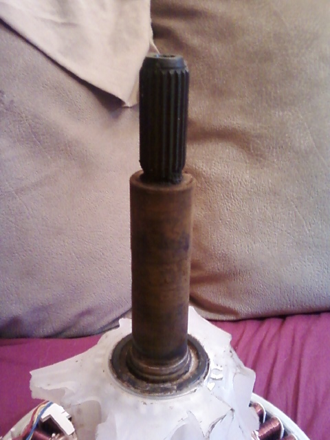
This shot gives a pretty good shot of the thickness of the F&P shaft. The Oasis is much meatier in design and the steel is a darker color leading me to believe that it is a harder material. It could be for rust resistance, or could just have been cheaper cost.
This one gives a good shot of a hall effect sensor on this. I assume it reads each phase that the motor runs. I would love to learn how to use this to monitor rpm and load, but I am nowhere near good enough with electronics to know what to do.
This one shows a pretty good shot of what was left of the machine. The tub is relatively brittle so after I strip it to just the tub and shaft assembly I beat the tub wth a sledge hammer and bust the assembly out. This proved to be a much faster way then the sawzall method, and was much easier. Word of advice: If you use this method remember protective gear. The peices that fly can be sharp and hard. Again broken down and allbearings removed you can melt that off. I will try to get pics and or video of that process.
This gives you a pretty good shot of the beefier Oasi shaft. Notice the lip at the bottom of the splines. The F&P is relativly close in spline diameter and main shaft diameter
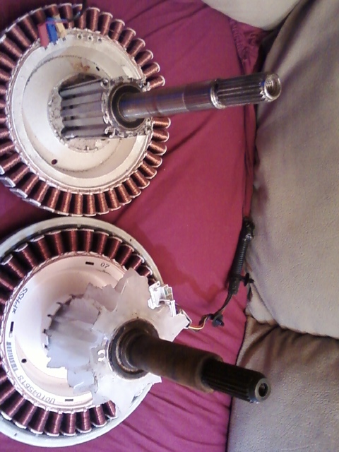
This shows both coil packs Side x Side. You can notice that one has 42 coils (the F&P) and one has 36 (the oasis) both of the Oasis coils and both of the F&P's I have are the same. The differences are the F&Ps I have each have a different shaft (one has a male screw on the agitator end, and the other has a female screw hole on the agitator end (at least they are common threads to each other so you can combine the shafts).
This is another shot of the remains from the Oasis machine. It shows the assembly as I keep them when I get to strip a washer for these parts.
When I get home and get my internet fixed I will update these with what they are...Edited by readyakira 2009-07-23
Don't you think Free/Renewable energy should be mandatory in new buildings? |
| |
readyakira
Senior Member
Joined: 17/07/2008
Location: United StatesPosts: 114 |
| Posted: 09:30pm 21 Jul 2009 |
Copy link to clipboard |
Print this post |
|
I noticed on these oasis machines whirlpool took alot of designs from other machines. Those motors look to be definatly made by the same company that makes ones for f&P The tub suspension these use is similar to GE top load washers, and the dust (water) shroud is identical to the one on the Fisher and Paykel. You can see in one of the pics the Oasis machines come with the iron cores already rounded as opposed to the F&P being flat. I need to get pics of the back sides of the hubs to show how the bolts and nuts are part of the hub and each out of 4 motors I have 3 different hub styles.
Don't you think Free/Renewable energy should be mandatory in new buildings? |
| |
readyakira
Senior Member
Joined: 17/07/2008
Location: United StatesPosts: 114 |
| Posted: 09:32pm 21 Jul 2009 |
Copy link to clipboard |
Print this post |
|
One other thing I should note. I wouldn\t attempt to touch the wires coming off the coils with your hands and spin the motor. I got a pretty surprising jolt doing that while holding a meter to the wires. I had no idea they could put out that much power at a low speed.
Don't you think Free/Renewable energy should be mandatory in new buildings? |
| |
Pukwudji
Newbie

Joined: 10/07/2009
Location: United StatesPosts: 20 |
| Posted: 03:22am 22 Jul 2009 |
Copy link to clipboard |
Print this post |
|
So what do you want for one of the Oasis units (assuming you want to sell any)? 
pukwudjivc@yahoo.com
-Brian V
Hillsboro, OR (USA)
KF7DUZ |
| |
readyakira
Senior Member
Joined: 17/07/2008
Location: United StatesPosts: 114 |
| Posted: 11:44am 22 Jul 2009 |
Copy link to clipboard |
Print this post |
|
You will need to do some research on just what combinations work. It looks as if you would need a F&P coil pack and oasis magnet hub. someone else would have to correct me if I am wrong.
Don't you think Free/Renewable energy should be mandatory in new buildings? |
| |
oztules

Guru

Joined: 26/07/2007
Location: AustraliaPosts: 1686 |
| Posted: 12:36pm 22 Jul 2009 |
Copy link to clipboard |
Print this post |
|
Readyakira
"This one gives a good shot of a hall effect sensor on this. I assume it reads each phase that the motor runs. I would love to learn how to use this to monitor rpm and load, but I am nowhere near good enough with electronics to know what to do. "
It is simpler than it looks. If you look at your Hall devices, and hold one so you are looking at it's face with the writing on, and the three pins facing towards the ground......
Then:
pin1 (left hand side) = + volts.. from 5-24v
pin2 (middle one) = neg volts (neg terminal)
pin3 (right one) = open collector output
So you hook your say 12v battery to the pos and neg terminals of the hall, and a resistor (say 1k) from the pin1 to pin3.... and you have a pulse sending device. As the magnets pass it, it will have a square wave output on pin3.
As one pole passes (say N pole) the transistor inside turns on, and shorts the pin3 to ground, and so no signal on pin3, as the next pole passes, it opens the transistor, and so voltage rises (through the resistor) and you get a + pulse on pin3.
Feed this into your digital multimeter with a frequency range, and you will generate the frequency number.
You will simply have to work out what that number means... and that will depend on how many magnets there are. One way is to measure the frequency while turning it a 1 rev/second and finding the divisor that way.
If you don't have a frequency meter multi meter then you will need a lot more technology handy 
...........oztules
Village idiot...or... just another hack out of his depth |
| |
GWatPE
Senior Member
Joined: 01/09/2006
Location: AustraliaPosts: 2127 |
| Posted: 12:46pm 22 Jul 2009 |
Copy link to clipboard |
Print this post |
|
Hi oztules,
The hall effect units, do not always have discrete components. The one I looked at was potted with a silicone type stuff. not easy to remove.
Probably better to use new components, of figure a way of using the original as is.
Gordon.
become more energy aware |
| |
readyakira
Senior Member
Joined: 17/07/2008
Location: United StatesPosts: 114 |
| Posted: 03:14pm 22 Jul 2009 |
Copy link to clipboard |
Print this post |
|
well I believe it has 6 or more wires... I think there is 3 sensors on that board... I will have to pull it tonight and get some pics up of it..
Don't you think Free/Renewable energy should be mandatory in new buildings? |
| |
oztules
Guru
Joined: 26/07/2007
Location: AustraliaPosts: 1686 |
| Posted: 10:42pm 22 Jul 2009 |
Copy link to clipboard |
Print this post |
|
Thanks Gordon,
They have to be fairly discrete, as there needs to be three sensors spaced the same distance as the magnets.
Akira,
It will need three sensors on the board to operate. There are only two usual ways for the mother chip to get spacial reference.... back emf from the coils (cunning) hall sensors (simple and usual)
There will be +, -, three signal wires.... and maybe a temp signal wire? (wild guess about the sixth wire)
Wish I had one to butcher.... errr.... look at....
If you had the washing machine it would be easy to follow the wires to the mother board... the sig wires would have to go to the processor, and the + and - would go to the power bus.... then simply use any one of the three sig wires and power it up via the power wires. There may be some shaping stuff on the board, but it should not matter.
It may be useful for those of you with a bent towards electronics, and actually have stators, to unravel the mysteries, and Gizmo can do a page for those who want to measure RPM.
I know one guy over here that has a stator, I will see if he still has it, and if it is complete. If so, I will do a how to if no-one else steps up perhaps.
Will be interested in the picks.
.........oztules
Village idiot...or... just another hack out of his depth |
| |
readyakira
Senior Member
Joined: 17/07/2008
Location: United StatesPosts: 114 |
| Posted: 02:17am 23 Jul 2009 |
Copy link to clipboard |
Print this post |
|
Weel here are some pics of the sensor...
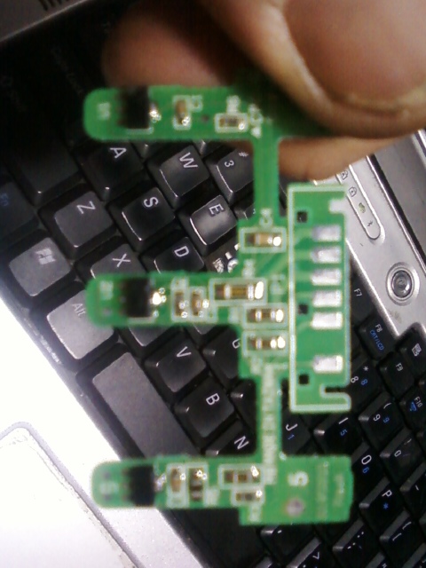
This shows a close up of the circuits It is the best I can get with a cell phone camera You can see that one of the six wires is seperate and 3 have large tracers and three have smaller tracers...
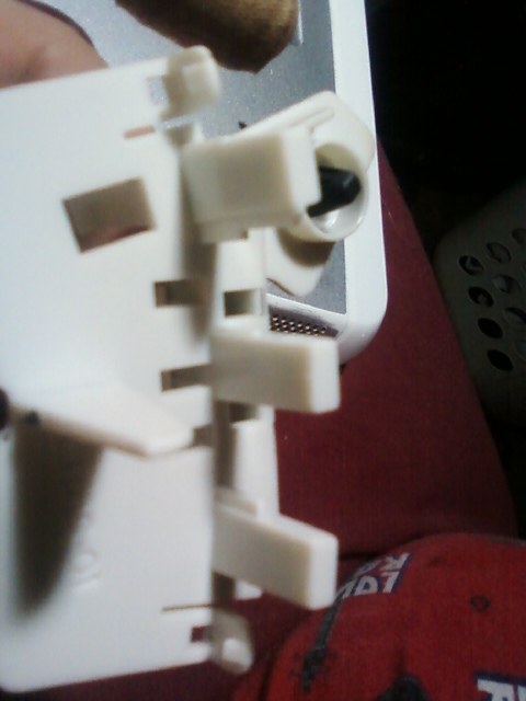
This one shows the plastic that encases the sensors. The fit neatly between the coils ends.Edited by readyakira 2009-07-24
Don't you think Free/Renewable energy should be mandatory in new buildings? |
| |
