
|
|
Forum Index : Windmills : Field Strength of Rotor Magnets
| Author | Message | ||||
Megawatt Man Senior Member Joined: 03/05/2006 Location: AustraliaPosts: 119 |
G'day all, Does anybody know whether the strength of the magnets in the old rotors is the same on F&Ps with 100 and 80 stators? When I know this, I can post an equivalent circuit of an 80 F&P for Gizmo's new page on design. Thanks Megawatt Man |
||||
| brucedownunder2 Guru Joined: 14/09/2005 Location: AustraliaPosts: 1548 |
Hi Megawattman,, As far as I know they(F&P) have made 3 different magnetic rotors-- First was with small Neo type ,white plastic housing and narrow singular strip type mags. I've tried to get these off ,but they are very firmly stuck on ,so I damaged them trying to remove them. Second. these were the most common types with Ceramic rectangular block magnets-4 individual retangular polarized magnets in the one "block" (These are the rotors that 99% of us would have) Third . The new type. These are similar to the second ones but of course have different magnets within the blocks,,-sort of a blunt arrow shape.. Now ,as for your question regarding the strength of magnets in the 3 different rotors, I reckon the first(Neo) rotors were weak. The second(common) and most recent ,I'd think they are about the same. But I guess you'll not find this out from F&P. Hope this helps Bruce Bushboy |
||||
| Megawatt Man Senior Member Joined: 03/05/2006 Location: AustraliaPosts: 119 |
G'day, thanks for that Bruce. Well, with a few assumptions and having gathered info from Dr Chalko's paper and tests carried out by blokes on this forum, , here's an equivalent circuit for a F&P using a .8 mm stator. N is the rpm at which the machine is driven. All the basic info used really needs to be confirmed by tests, particularly a no load and loaded test at known constant speed. But, this is a start to design info that might be posted on Gizmo's new discussion thread. 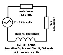 Megawatt Man |
||||
| Megawatt Man Senior Member Joined: 03/05/2006 Location: AustraliaPosts: 119 |
So what you can do with this equivalent circuit is calculate things, like in the following. Using 713 rpm and a load current of 2 amps, results in a no load voltage of 535, terminal voltage of 513 volts or a power output of 1026 watts. There are about 62 watts for core losses and maybe another 30 for bearing friction (again from Dr Chalko) plus the copper loss of about 23 watts to add to power input. Efficiency would be about 90%. There is still some way to go! Please check the numbers if you desire and tell me of any mistakes - I really want to get this right. Megawatt Man |
||||
| FandPwithPVC Regular Member Joined: 09/09/2006 Location: Posts: 64 |
Fisher and Paykel have NEVER I repeat NEVER used Neo Magnets in any of there Washing Machines. Regards Dennis L |
||||
| Gizmo Admin Group Joined: 05/06/2004 Location: AustraliaPosts: 5182 |
They did once use a neodynium magnet, but very weak compared to todays neo's. It surprised me, as the magnets in the early 100 series stators didn't seam any stronger than the ceramics in the 80 and 60 series, but this article talks with one of the F&P designers, interresting read. It mentions the evolution of the smart drive in the last few paragraphs. You can also find a link to the article on my links page. I was going to do a test this afternoon, but the hall sensor I have is stuffed. I was going to sit the hall sensor in the middle of the magnets in the 100, 80/60 and late model 48 magnet hubs. This would have given a relative magnet strength of each different model. I will try to grab a new hall sensor from Dick Smith this weekend and do the test. Glenn The best time to plant a tree was twenty years ago, the second best time is right now. JAQ |
||||
| Megawatt Man Senior Member Joined: 03/05/2006 Location: AustraliaPosts: 119 |
G'day again. People reading my posts will have noted that I am not a bloke that encourages use of F&Ps unmodified, because of the high voltages involved. The equivalent circuit posted above is for an unmodified machine, because all the resource material came from experiments on unmodified machines. For a machine rewound so that each star leg comprises 7 branches of two coils in series, all then connected in parallel, the generated voltage would be 0.107N: resistance would be 0.118 ohms; and reactance would be j0.00145N ohms. The current chosen in my calc of 2 amps for an unmodified machine would rise to 14 amps. Similarly, if all the 14 coils were reconnected in parallel, we would have generated voltage 0.0536N; resistance 0.414 ohms: and reactance j0.005N ohms. The current would be 28 amps. Again, please tell me about mistakes! Megawatt Man |
||||
herbnz Senior Member Joined: 18/02/2007 Location: New ZealandPosts: 258 |
Hi A equivalent cct would be fantastic. However in my mind i feel it will be more complex than assuming the emf generated constant and using the impedance to calculate output voltage. In all permanent magnet generators and particularly the smartdrive there is a reduction in the field flux as the opposing ampere turns increase due to load current this has a drastic effect on the generated emf much greater than the potential drop due to the impedance. The drop in field flux is complex but one the opposing mmf from the stator reduces the effective mmf of the permanent magnets also smartdrives are prone to leakage flux the opposing flux makes it easier for the flux to jump to the neighbouring pole and not go via the stator. we can come up for constants that can be included in the equivalent cct that reduces emf on load current. I will set my test rig up in the near future and see if a constant can be determined and if itis the same at varying loads Also another issue is the different characteristics when feeding resistive loads to battery charging where only the peaks are being used Cheers Herb |
||||
| Megawatt Man Senior Member Joined: 03/05/2006 Location: AustraliaPosts: 119 |
G'day herbnz, look on the subject"Field Strength of Rotor Magnets" annd you can see my first posted attempt at an equivalent circuit. The N in the expression comes from Dr Chalko's test at 713 rpm. I accept your description of partial cancellation of magnetisation by pole currents and also of incomplete and displaced flux linkages. I am most interested to see if we can derive some empirical relationship to substitute for my N. Of course, my eqivalent circuit is for one spider/rotor combination only and there are a lot more. Have you looked at the alternators that people are making overseas using pairs of motor vehicle disc brake rotors upon which are fixed neo magnets of opposite polarity arranged with a gap of some 25mm between them, into which space are placed three phase connected air cored coils? I must be missing something here, I just don't follow why they don't include even blocks of ferrite in the coils. The increase in magnetisation would be enormous. Have you any explanation for me? On the point of transient current pulses, yes, this must also occur. A related idea is using classical power supplies to feed loads that don't prtesent a high demand. Unlike SMPS though, nobody complains about harmonics and transients, although the waveforms look the same. I guess I'll work it out one day! Megawatt Man |
||||
| herbnz Senior Member Joined: 18/02/2007 Location: New ZealandPosts: 258 |
Hi Mega I saw your cct above what sparked my comments. My thoughts at the moment are to run controled tests on one coil only measureing out put at different speeds and loads. I would start with 1mm stator as its all I have here but if works out repeat with others. We should then be able to see if we can come up with equ cct one coil. Could you point me to Dr Chalko's paper i have seen it but a long time ago. I remeber being a little bemused by the effort to measure input power, I very simply mount and drive the gen on its shsft then use a spring balence to hold stator input power then = 2*pi*n*T/60 watts.As accurate as the spring balence is. The disc brake gens i have not seen but seen others on this style is it axial type they call it, i guess that most space is taken up with windings 25 mm tho thats huge. I have often dreamed about a soft magnetic compound we can mold like resin and imbed windings. Anyone know if the likes exist. I have thought mixing cast iron dust in resin we dont really need ferrites as frequence relativly low. Regards harmonics and smartdrives I will at some stage have a lot to say in relation to how they affect batteries. I must say it is most satisfying to have found a forum where there is a understanding of the fundementals. Cheers Herb |
||||
| Megawatt Man Senior Member Joined: 03/05/2006 Location: AustraliaPosts: 119 |
G'day herbnz, Search on "Optimizing a Permanent Magnet Alternator for micro-hydro application", the name of his paper. His objective was to reduce the output power to more closely match the energy available from a small hydro setup, so he cut off half the poles from the spider for a start. Still, extrapolating his results is possible as you will see. Can't wait to see what decrement there is in output voltage as load increases, due to the imperfect flux cancellation. Assuming this decrement was linear( a giant assumption, but one to start with) my equivalent circuit generated voltage would equal 0/75N - (0.75N - Efl)*I/Ifl, where Efl and Ifl are full load voltage and current. For a given N, we could have then, output voltage E = 150 - (150 - 110)*I, or 150 - 40I. Plugging this into the equivant circuit formula would give 150 - 40I = R + jX, R and X being total internal and external impedance quantities. Initially, knowing R would allow us to calculate X and then we could perform calculations for other load conditions. Mmmmm. By the way, if the equivalent circuit can work for the I R and X quantities, power calc would still have to allow for bearing and core losses, windage apparently is negligible. OK, just how much is the decrement? Megawatt Man |
||||
| brucedownunder2 Guru Joined: 14/09/2005 Location: AustraliaPosts: 1548 |
Wow,, Youse guys are well above me--- I can't even understand what yer talkin 'bout sitting on the side walk and waiting for some simple solutions Sorry, Bushboy. Bushboy |
||||
| herbnz Senior Member Joined: 18/02/2007 Location: New ZealandPosts: 258 |
Hi Mega Man you have some typos in formula but Iam sure your right but I have not sat down with it yet to understand. I have started testing I am using 1mm stator I see your cct .8 but Dr Chalky was 1mm. I have done some very tentative testing using 4 coils of one phase in series I measured inductance using a signal generator (sine wave did not trust my modified waveform ) used 370hz 0.0012H 0.5 Ohms resistive 4 coils in series. Ran a test at speed 160rpm 74 hz interesting your method calculating impedance then voltage drop worked up to about 3.5 A then voltage drop started to increase rapidly will not give figures yet only really setting up. An initial thought tho is that maybe the poles are saturated at no load and flux does not start decereasing until our opposing mmf starts to move the poles out saturation. i will take a while to complete testing but will put all in a spread sheet send it Sorry Bruce hopefully it will come out to something simple Cheers Herb |
||||
| Megawatt Man Senior Member Joined: 03/05/2006 Location: AustraliaPosts: 119 |
Hello herbnz, yes, sorry about the typos, I am a bit clumsy on the keyboard sometimes. Also get a bit excited about the topic, so don't worry about the actual spelling. The first expression in the formula should read 0.75N. Then, just to see how the formula might work, I have assumed a no load voltage of 150 and a full load voltage of 110. So far your tests show that linearity is just not on, maybe two straight line rules could apply. brucedownunder2, the stuff we are talking about at present is hopefully to set down some rules to apply when we set off to create an alternator from a machine about which we know little. We are looking for a formula for each configuration of F&P that you can plug numbers into at the design stage, so you could get a stator and modify it, put in neos of a specified strength and drive it at a known speed to produce a predictable output. So that's why you might have seen in my posts some pretty strange requests for test results, mostly because I haven't got an F&P yet and when I get one, I will still not be able to forecast performance of units that use the different windings and magnets. I am particularly interested in how your 36 pole unit goes. Mr F&P makes much of claims to efficiency of his new motors. That means that they are rated lower in power input and output, so I suspect that they may not produce great outputs as alternators. My gut feel is that your results using neos that produced 600 watts output and more are up there but I want to be able to say, Fellows use neos type xxx, drive the machine at yy rpm and expect zz watts output. Seems like it would save some trouble. All the best. It is my purpose in life to use what I've got in my head for the good of my fellows and when we get to the end of the study, I will try so hard to explain it that it mightn't be funny. Stay with us Bruce,it won't hurt. Megawatt Man |
||||
wind-pirate Senior Member Joined: 01/02/2007 Location: CanadaPosts: 101 |
Hi Guys!! REsearch And development. Thats where the answer is. Keep up the Good work. Remember every failure, is one step closer to the answer. THE Pirate. stealing wind & solar energy is fun |
||||
| brucedownunder2 Guru Joined: 14/09/2005 Location: AustraliaPosts: 1548 |
Hi megawattman and herbnz,, Really appreciate your efforts and will be taking a keen interest in them --Just tongue-in-cheek stuff about the numbers Etc. I've got the new stator up --re-connected into 6 groups of 2 poles in series-3 phase. Dismal wind conditions,even though it turns in what seems no wind at all. Dismal o/p ,nil actually,can't get it past around 15v. But remember there's no wind , if we get some sort of a storm here ,then that may alter things ? So , this 2 poles in series is about half as good as the 4 poles in series. The 4 poles in series climbed to 30-40 volts real easy,even though the o/p in Amps was max out at around 3-4. (at least the 4 poles in series gave something, this latest 2 poles in series is yet to give anything. Keep up the good work,thanks Frustrated (bruce) Bushboy |
||||
| herbnz Senior Member Joined: 18/02/2007 Location: New ZealandPosts: 258 |
Hi Mega watt man and others interested Some raw data in case you got time to feed into spread sheet and analyse i can carry on taking more readings at different speeds. Ok 4 1mm 44 turns coils of one phase in series no rectifiers AC values. 200 RPM 100Hz list values Vout,Iout-7.2,0.28-7.14,0.64-6.870.92-6.66,1.42-6.24,2-5.3,3 .1-3.68,4.6-1.39,6.09-1.1,6.2 737 RPM 344 Hz 24.15,0-22.09,0.87-21.48,1.33-20.31,1.99-18.05,3.37-15.82,4. 21-12.71,5.2-8.95,5.99-4.82,6.67-0.85,7.01 My measurement 4 coils Z=2.9 (f=370hz-I=126ma-V=0.36) dc resistance 0.5 i calculate L= 0.0012H I want spend more time on inductace tho I measured with rotor on random position. If the poles are saturated at at no load its going to be very different if under a pole. We have taken on a very complex beast i think. But lets see how it goes. my be idea to present graph of one coil and formula to convert to combinations. Cheers Herb |
||||
| Megawatt Man Senior Member Joined: 03/05/2006 Location: AustraliaPosts: 119 |
G'day again Herb. Thanks very much for your efforts. This is a very jelly-like parameter to come to terms with. If you look on the thread Electronics-F&P Inductance you'll see a report by Gizmo placing inductance per coil of a 1 mm 44 turn coil at 1.2mH. I don't know the frequency at which his measurements were made and I don't know whether the spider was inside a rotor at the time. RossW responded indicating some disagreement, but not too serious. RossW's measurement was on an assembled machine but I don't know whether it was running at the time. I offer the following two ideas for consideration. 1. Inductive reactance is due to the proportion of magnetic flux available to work but doesn't quite get there because it doesn't couple with the coil - in other words, it's leakage flux. Now as you point out, your preliminary measurements were at one position of rotor/stator and you may measure different values if you move the rotor to another position. I want to go one step further and say that the flux leakage that influences alternator performance is the leakage during operation of the machine - ie while it's running. So that means we need to perform load measurements on the machine and use those results to calculate inductive reactance. 2. My sunconscious got to work last night while asleep. You pointed out recently that the flux linkages change as alternator output current causes changes in flux paths. This means that the inductive reactance of the machine is a function of output current. I hope it's not too much of a dependent variable, otherwise we'll have a series of equivalent circuits to use as load changes occur. Not only would we have generated voltage changing with load, we would also have inductive reactance being a dependant variable. If that is right, even measurements of load conditions from which reactance is calculated are of dependant variables and arriving at a value to use in practice becomes an iterative process. What do you reckon? Megawatt Man |
||||
| herbnz Senior Member Joined: 18/02/2007 Location: New ZealandPosts: 258 |
G'day Mega look at the load data i repeat it here tests done at 200RPM & 737 RPM voltage out against current drawn its quite revealing not much drop in voltage then about 5 to 6 amps all starts collapsing. Some raw data in case you got time to feed into spread sheet and analyse i can carry on taking more readings at different speeds. Ok 4 1mm 44 turns coils of one phase in series no rectifiers AC values. 200 RPM 100Hz list values 737 RPM 344 Hz 24.15,0-22.09,0.87-21.48,1.33-20.31,1.99Vout,Iout-7.2,0.28-7 .14,0.64-6.870.92-6.66,1.42-6.24,2-5.3,3 .1-3.68,4.6-1.39,6.09-1.1,6.2 -18.05,3.37-15.82,4. 21-12.71,5.2-8.95,5.99-4.82,6.67-0.85,7.01 have tried tests on impedance rotor on and off different positions range 2.8 to 3.4 ohms testing at 370 hz as before. Not as great a change as i thought may be there. Cheers Herb |
||||
| The Back Shed's forum code is written, and hosted, in Australia. | © JAQ Software 2026 |
