
|
|
Forum Index : Windmills : F&P Rotor Mounting
| Author | Message | ||||
| nweeks Newbie Joined: 22/01/2007 Location: AustraliaPosts: 36 |
I have to mount a rotor on the back of a trailer stub axle wheel plate, and I'm trying to work out the best way to do it. The main issue is, the rotor's surface is sloped away from the wheel plate in the center, possibly making the use of nuts and bolts difficult. 

The rest of the turbine is Here Any ideas? Nigel Weeks nweeks at karbonit dot com |
||||
| Gizmo Admin Group Joined: 05/06/2004 Location: AustraliaPosts: 5182 |
Very good work Nigel. Had a look at your link and you have been busy 
Your design is very similar to my first F&P windmill. These photos are not the best, but they may give you an idea how I did it. 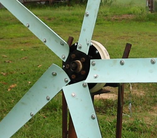
I cut the center out of the magnet hub, except for a rim of about 1 inch. This was then bolted, using the existing drain holes drilled out to suit 1/4inch bolts, to a 2mm steel plate, which in turn bolted to another steel plate with holes to suit the studs on the wheel hub. 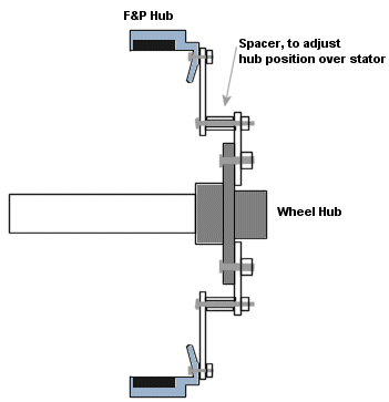
I could adjust the spacers to align the hub over the stator. It worked ok, but I remember I had problems with the hub not centered correctly. Glenn The best time to plant a tree was twenty years ago, the second best time is right now. JAQ |
||||
| brucedownunder2 Guru Joined: 14/09/2005 Location: AustraliaPosts: 1548 |
Hello Nigel,, very good work you have done there. What you have done with the trailer stub axle and hub is a very strong set-up ,but from what I can see you are going to have trouble getting the Rotor's magnets fully positioned. That thick hub plate will prevent the Rotor from being positioned. The one idea I have is for you to build a steel sleeve that could be fibreglassed to the cut away ring of magnets and this sleeve then having a end plate that bolts to the hub--fairly complicated job ,,and it has to be very accurate. From previous experience, these plastic rotor hubs are a bit too flexable to be supporting windmill blades. Trev's cast blade holder hub seems to be the best idea that I've seen ,but you'd have to rethink your engineering set-up,as this hub uses the F&P splined shaft. I've got one of his hubs and his bearing holder casting which ,by the way ,can accomodate two F&P stators. I'd recommend these two items . Bruce Bushboy |
||||
| nweeks Newbie Joined: 22/01/2007 Location: AustraliaPosts: 36 |
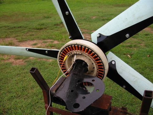
The rotor will go between the wheel plate and the stator, and the wheel studs themselves will be holding the blades. 
It'll fit just nicely - well, the old series of rotors do, hopefully the new rotors have the same dimensions...;-) I'm thinking I might tweak Gizmo's idea, and use bolts with a sleeve cut at an angle to suit the inner slope of the rotor, so the force doesn't pull against the high side. of the hole. Going to order a new rotor today! Wish me luck! Nige. Nigel Weeks nweeks at karbonit dot com |
||||
Prof Newbie Joined: 01/12/2005 Location: AustraliaPosts: 33 |
Hi Nigel, I have posted this picture before and it shows how to support the plastic F&P rotor to keep it stable on a stub axle. The rotor will still distort if it is not in operation, or left lying on its side or if not strongly supported. In the picture it is screwed to a thick alloy plate which in turn is bolted to the wheel hub. Even then if it is not spun for a period of time occasionly then re- centering is needed. 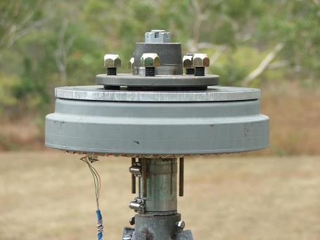
Prof I know boats!! |
||||
| nweeks Newbie Joined: 22/01/2007 Location: AustraliaPosts: 36 |
Hi all! I got my new rotor yesterday, and proceeded to chop the center out. The differences between the rotors is quite obvious: 
I sat the hub on the rotor, and marked out where I had to cut out: 
Predrilled, checked, then drilled the rest  
Then gently, with the jigsaw, knawed away at the remaining material. 
Unfortunately, there's 6 studs on my wheel plate, and 10 reinforcing ribs on the F&P rotor, causing two ribs to sit up on the back of the studs. 
So, out with the file, and put notches in two ribs(opposite sides for balance) to cater for the back of the studs. 
Now, it sits nice and flush 
Here's how it fits together at the moment - just need to fix the rotor to the wheel plate  
See the hires images here Nigel Weeks nweeks at karbonit dot com |
||||
| Gizmo Admin Group Joined: 05/06/2004 Location: AustraliaPosts: 5182 |
You know, I wonder if there is a brake drum that the F&P hub would fit into? It sure would make this a lot easier, it will be dead center and never drift out of center, and be stronger in the long run. Even if the drum is slightly smaller, a brake machine shop could machine it out to suit. If the drum is a little big, then shims could be used. Just an idea. The F&P hub is 275mm od, give or take. Glenn The best time to plant a tree was twenty years ago, the second best time is right now. JAQ |
||||
| nweeks Newbie Joined: 22/01/2007 Location: AustraliaPosts: 36 |
Brake drum...I bet a landcruiser one would be awfully close... Anyone got one? Fancy measuring the ID of the drum? You'd save: UV exposure of the rotor no fear of it flying to pieces mechanical protection if it came down in a storm nice flywheeling action to help overcome cogging. gyroscopic dampening in wildly changing wind directions(possible below any measurable benefit...) Nige. Nigel Weeks nweeks at karbonit dot com |
||||
| brucedownunder2 Guru Joined: 14/09/2005 Location: AustraliaPosts: 1548 |
Nice work Nige. I was wondering how you are going to make it easy for you to remove the Rotor ,the magnets "Hold" a fair bit ?. I have this new Rotor and initial observations show that they are not as powerful as the original , so a guy like yourself might consider a Neo retrofit some time later ?. I've a Neo old style Rotor and in a decent wind it delivers heaps of output,. I tried a neo conversion using 36 evenly spaced magnsts ,but unfortunately the gap between them was a wee bit too wide and I got no output,maybe working with wider magnets to reduce the "gap" would be much more successful. You are doing great work , Bruce Bushboy |
||||
| dwyer Guru Joined: 19/09/2005 Location: AustraliaPosts: 575 |
Hi Bushboy said I tried a neo conversion using 36 evenly spaced magnsts ,but unfortunately the gap between them was a wee bit too wide and I got no output,maybe working with wider magnets to reduce the "gap" would be much more successful. Well You are right as l had same problem too so l decide to scrap the ideas on my alloy hub for awhile 
Dwyer the bushman |
||||
| nweeks Newbie Joined: 22/01/2007 Location: AustraliaPosts: 36 |
Hi guys, This is the second 7phase mod I've done, but I don't follow Gizmo's instructions quite to the letter. If you take a look my turbine the page, the first rotor also has rectifiers connected to the common rail. Without also pulling power from this rail, yes, output is very limited. The reason being is thus (and highly simplified, assuming the respective has just completed it's approach, thusly coil if at full flux): Phase A has a north magnet, so it's endpoint is +ve Phase B has a south magnet, so it's endpoint is -ve As the startpoints of all phases are joined, the net voltage from endpoint A to endpoint B is (-1 + 1) = 0. And yet, a healthy amount of power is being produced by each coil... But, if you rectified the star point/common rail as well, your total sum between endpoints would still be 0V, but you'd have both the +1 and the -1 sending output down your rails. Don't believe me? Grab a bridge rectifier, hook both the AC lines to the star/common rail, and the +ve and -ve outputs to your output rails. As for the mounting system, I'm envisaging three clamps 120degrees around the F&P rotor, with tapped holes in the circumference of the wheel plate, allowing a cap-head screw to do the following: Provide both axial and radial tension to keep the F&P rotor firmly against the wheel plate. Provide a method of adjusting the F&P rotor around in respect to the wheel plate. Nothing fancy, just a little bit of steel, almost like an S bend, but with a square angle for gripping the F&P rotor. Now to find a 5/16 tap to tap out the holes... ...Possibly might do six clamps to reduce the possibility of only three clamps squashing the F&P into a delta-shaped circulonic trimetadoid...;-) Nige. Nigel Weeks nweeks at karbonit dot com |
||||
| brucedownunder2 Guru Joined: 14/09/2005 Location: AustraliaPosts: 1548 |
Hi Nigel, any chance of you posting a schametic diagram of how you re-configured the F&p --I'm a bit dense in understanding your wording,sorry. I'd certainly try it as I'm getting frustrated with the new Stator / rotor rewired outputs. The original stators ,I've done with 4 different 7 phase combinations and still get low output with the new 36 magnetic Rotor. Like your work , wish you success Bruce Bushboy |
||||
| nweeks Newbie Joined: 22/01/2007 Location: AustraliaPosts: 36 |
It's probably best with pictures. These are on my page, but I'll link to them again here. The seven phase mod involves tying the start of seven phases together, yeah? 
As you can see, in the center of the pic, there's the large wire joining all the phases together. Then, you can see the diodes connected to it, which are then connected to the +ve and -ve rails. To prove that these diodes have an effect - single ones got hot, so I soldered on a second one for each polarity. The rest of the mod is the same - series connect as many phases as you want (I do three, as it allows me to have two sets of DC outputs per stator - easy quasi-delta/star connections by parallel or series of the two DC outputs) It's all in the Pictures! Nige. Nigel Weeks nweeks at karbonit dot com |
||||
| brucedownunder2 Guru Joined: 14/09/2005 Location: AustraliaPosts: 1548 |
Thanks Nige.. It appears that in that photo you are using the big 1mm wire stator - bugger,gave my last old one away ,hahaha. I've actually reconfigured a 1mm stator into 7 phases ,so I'll take a look at that and see if it's possible to go back and redo it. Any "up-the-tower" results with the above Stator yet???. Be interesting to see Thanks Bruce Bushboy |
||||
| nweeks Newbie Joined: 22/01/2007 Location: AustraliaPosts: 36 |
Yep, I gave the first one to my Dad for tinkering. My current one (at the bottom of the page) has tiny wire, but it'll be ideal, as the cable run will be fairly long. No results other than spinning the one I gave Dad in his lathe - lit up a 100w car spotlight to full brightness(14VDC) at 180rpm, with only half the stator wound. Parts I need for mine are: 50mm OD pipe for yaw mount 50mm bore flange bearings to clamp onto the yaw tube Big hinge for the tail(passive furl, similar to Gizmo, but less complex) Tail of some sort. Hopefully, I can get the rotor mounted to the wheel plate tonight - the missus has got good TV to watch...;-) Nige. Nigel Weeks nweeks at karbonit dot com |
||||
| The Back Shed's forum code is written, and hosted, in Australia. | © JAQ Software 2026 |
