| Author |
Message |
brucedownunder2
Guru

Joined: 14/09/2005
Location: AustraliaPosts: 1548 |
| Posted: 09:47am 06 Jun 2007 |
 Copy link to clipboard Copy link to clipboard |
 Print this post |
|
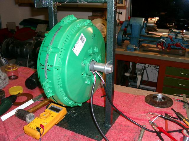
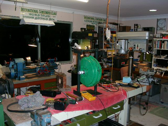
Well, crew , I finally got the welding gas and now I've put together a 'stand" for the Seeley motor that Dennis Latham has discovered.
I'm still in the process of lathing a suitable "timing-belt" gear for it ,Motor on the lathe carked it this afternoon-will take a while to change over ,Etc.
I spin this thing by hand ,connected to my "fluke" ddm and read 34 v 's--,,so that's fairly promising !!,just turning it slowly gets in the 11--25 V range.
Anyhow ,,we'll see.....
Bushboy |
| |
brucedownunder2
Guru
Joined: 14/09/2005
Location: AustraliaPosts: 1548 |
| Posted: 10:34pm 06 Jun 2007 |
Copy link to clipboard |
Print this post |
|
Hello,
I would like to contact any of the people that bought these motors ,to exchange idea's . If anyone has set one up on a test bed ,could u post something about it,please??
Bruce
Bushboy |
| |
Storm

Regular Member

Joined: 12/09/2005
Location: AustraliaPosts: 43 |
| Posted: 12:41am 07 Jun 2007 |
Copy link to clipboard |
Print this post |
|
Hi Bruce,
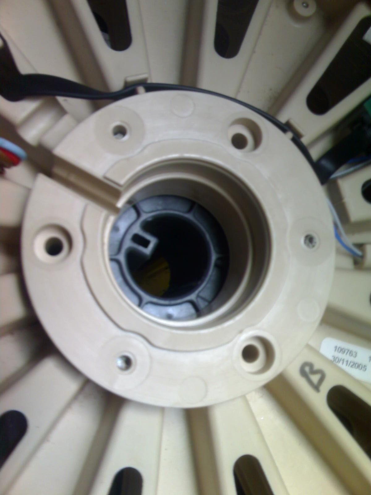
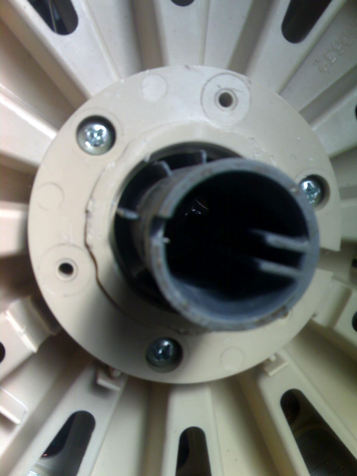
I haven�t had a test rig setup yet, I'm still in the building phase, shaft strength was my main concern.
Firstly I cut a 32mm shaft down the length (refer to previous seeley post) as I don�t have a lathe with the idea to chisel the plastic key from the inside, the problem was the 25mm shaft didn't fit inside the new ID (so close), so I sent a piece 32mm to the machine shop to get lathed similar to yours. I haven�t got it back yet.
The other thing I've began is to remove the plastic bearing centres and run 40mm tube straight through the bearings, the tube needed to be reduced to ~39.5mm to suit the bearings which I was able to do with a file while spinning the tube and regularly slipping the covers on to check fit, 100mm aluminium disc with some grub screws will need to be made to hold the stator, three bolts will go all the way through.
One of the plastic centres will need to be cut out with a hole saw as it was installed before the copper was wrapped.
When I saw Dennis he was building a test rig to measure output, I wonder what results he has come up with so far?? Sounds like from your tests we may need to run delta?? I'm just not at that stage yet mate.
Glen SA.
 |
| |
herbnz

Senior Member

Joined: 18/02/2007
Location: New ZealandPosts: 258 |
| Posted: 03:32am 07 Jun 2007 |
Copy link to clipboard |
Print this post |
|
Hi
I dont know how you measure input power I will give my method that is easy and accurate. I set the unit in the lathe or drill press by clamping shaft in chuck. leaving the housing free to rotate actually i usually put some stop to only allow limited rotation. i then get a spring balance set scales arrange so these attach to outer housing and pull in a direction that is tangential to the unit and attach other end to a fixed point. when i start the lathe the scale will measure the input torque force in scale * distance to centre shaft force in newtons distance metres newton 9.81 kilograms input power = 2 * pi * rpm * torque / 60 = watts
one point scales must read zero before running . be at tangent to housing for all readings
you will really see how your bearings seals gobble up power at least 30 watts in fp
herb
|
| |
brucedownunder2
Guru
Joined: 14/09/2005
Location: AustraliaPosts: 1548 |
| Posted: 09:36pm 07 Jun 2007 |
Copy link to clipboard |
Print this post |
|
Thanks Glenn and Herb,
Glenn ,I'm using the plastic bearing sleeves for a couple reasons, . They are a nice firm fit ,are secured and "keyed" in a perfect central and stable position.
And, the housings locked into the outer green shells have a crinkle washer to centralise and match the bearings perfectly.
What is your reason behind using a straight through shaft?.
I also cut and re-connected the six in's and out's of the 3 phases to 2 lengths of 3 core ,bringing them out so as to be able to re-configure as necessary.
I now get 50 v dc spinning by hand through the rectifiers. Get around 17 v dc just turning slowly with 1 finger..
work has stopped for a few days -- wedding guests and many chores to do ..
Bruce
Bushboy |
| |
Bryan1

Guru
Joined: 22/02/2006
Location: AustraliaPosts: 2101 |
| Posted: 05:16am 17 Jun 2007 |
Copy link to clipboard |
Print this post |
|
Hiya Bruce 
Well mate Dennis called up today and now I've got a couple of seeleys here to play with so in the next few weeks I'll have some new idea's as Dennis and I are working out a simple cheap way to set the seeleys up.
Cheers Bryan  |
| |
brucedownunder2
Guru
Joined: 14/09/2005
Location: AustraliaPosts: 1548 |
| Posted: 07:30am 19 Jun 2007 |
Copy link to clipboard |
Print this post |
|
Hi crew, I today set about finding a way to re-configure these windings like we have done to the F&P motors--not easy.
Anyhow,, I cut the windings around where I thought was appropiate ,at the end of the 10 Th winding and wound it onto a spool (coke bottle).
I've now got a few ,6 , coils of windings ,some continuous ,some broken, ----you have to work out which way to unwind them , tricky,,.
I'll rewind the coils with the same size wire from F&P stators --they are not varnished like these and seem to be more friendly in the rewinding exercise...
Haven't done any tests so far ,,so here's hoping for a good result----
Not even in the air yet ,just on my work bench ,so we'll have to be patient..
Bruce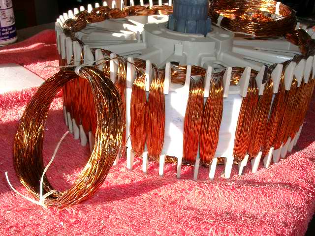
Bushboy |
| |
Gill

Senior Member
Joined: 11/11/2006
Location: AustraliaPosts: 669 |
| Posted: 11:07am 19 Jun 2007 |
Copy link to clipboard |
Print this post |
|
D'day Bruce and other lucky B's,
Just to give those of us without one some reference, as supplied, how many wires are coming out and what is the internal connections and configuration please?

was working fine... til the smoke got out.
Cheers Gill _Cairns, FNQ |
| |
Storm
Regular Member
Joined: 12/09/2005
Location: AustraliaPosts: 43 |
| Posted: 12:33pm 19 Jun 2007 |
Copy link to clipboard |
Print this post |
|
Bruce did you notice the stators are marked different wattage not the magnets or rings, the ones I received are 500w and 1500w they are different coloured wires. The 1500w seems to use touch heavier wire can you tell if the magnets are any different? Maybe its only the stators are different? |
| |
brucedownunder2
Guru
Joined: 14/09/2005
Location: AustraliaPosts: 1548 |
| Posted: 09:00pm 19 Jun 2007 |
Copy link to clipboard |
Print this post |
|
Hi Gil and Storm.. and crew ..
Yes , there are differences between rotors,stators.
First,,magnets ,,the 1500 's magnets seem to be 10mm longer than the small 500 watter.
Second , wire,,same here ,1500 's wire is the next gauge up from the rest---I think. haven't looked at the 1100,yet.
Storm,, the configuration 's are 3 Phase pigtails terminating onto coloured leads. The 3 phase "star" pigtails just terminate together and are heatshrunk for insulation.
What I'm trying to do is find a way to unwind as few as possible coils to bring out the "starts" and "finish's" ,so we can re-configure like we do with the F&P.
Cheers
Bruce
Bushboy |
| |
