
|
|
Forum Index : Windmills : Dummy load suggestion.
| Author | Message | ||||
| GWatPE Senior Member Joined: 01/09/2006 Location: AustraliaPosts: 2127 |
Hi Harald, The 20 or 28 ohm resistance will not load very much on a 24V system. I would probably need 15 of the 28 ohm resistors in parallel on my mill. Each 28 ohm resistor will dissipate around 28W on a 24V nom. system as a dump load at the expected dump voltage of around 28V. The resistor is probably designed for an instantaneous peak power power of 1.5kW at 200V. This is why the resistor is designed to be immersed in water. The power stored in the drum would fall at an exponential decay rate, so the total power dissipated by the resistor would be low. This would be a way of using these junk resistors. Supply may eventually be a problem though. The dump load still has to be matched to the expected maximum mill output. cheers, Gordon. become more energy aware |
||||
| carl1 Regular Member Joined: 16/04/2007 Location: AustraliaPosts: 79 |
Hi Gordeon This resister is not designed to be submerged!!!It sits in an outside slot of an extruded aluminum tube where the water flows throught the inside of the tube. You are right that you will need a dozen or more to dissipate a resonable load. have a look at one and it's easy to shorten the wire inside the glastube to adjust the needed resistance. cheers harald  |
||||
| KiwiJohn Guru Joined: 01/12/2005 Location: New ZealandPosts: 691 |
Hmmm.... if you just want a temporary load that can be adjusted for resistance and that can handle all even the biggest mill can produce how about a salt water bath? I have seen these used for testing a diesel gen set where they hung electrodes in a container then added salt water. Adding salt increased the load (reduced the resitance). I know it was a lash up as they had 4x2s on top of open oil drums but I cant recall what they used as electrodes. Stainless steel scrap would be good I suppose. |
||||
| GWatPE Senior Member Joined: 01/09/2006 Location: AustraliaPosts: 2127 |
Hi Harald, I do not intend looking at these resistors as there are plenty of other options. I would expect that the wattage of the original resistor was calculated for the specific task. If you reduce the resistance in the same package and have the same voltage across it, then the power to be dissipated by the package will have to increase. This would probably compromise the device. become more energy aware |
||||
Trev Guru Joined: 15/07/2006 Location: AustraliaPosts: 676 |
There is a lot of talk here, but in simple language, how does someone go about making a simple resistance wire load?? What are the basic electrical principals?? Voltage?, Amps?, Ohms?, derived from where?? I can supply Nickel/Chrome resistance wire $2.80/4m, resistance of 13.77 ohms/m and I am sure people can work out the physical winding onto and old ceramic tile or something, but how does one know how long the wire should be, and how many wires in parallel should there be? Trev @ drivebynature.com |
||||
| GWatPE Senior Member Joined: 01/09/2006 Location: AustraliaPosts: 2127 |
Hi Trev, The most important component is the total continuous power that is likely to be dissipated and the voltage. power = volts x amps = volts^2 / resistance = amps^2 x resistance NiChrome wire increases resistance with increasing temperature. This means that the load presented will decrease with power dissipation, as the wire heats up. Windmill runaway is possible in storm conditions if the power dissipation of the load is inadequate. Assume the windmill produces a Max 250W, has mechanical furling at the peak power. It may have a rotor dia of 2-3m. Assume the dump load is enabled at 28V on the battery. The current that has to be diverted then is amps = 250 / 28 = 8.93 The resistance is R = 250 / 8.93^2 = 3.13 ohms For the wire that you have specified You will need 0.227m for the 3.13 ohms. This wire length will glow red and will not dissipate the power adequately. The wire is quite thin. I would rate the wire for a temperature rise of 100 degrees only. It can take more, but could pose a fire risk. If you double the length and place 2 lengths in parallel then the resistance stays the same, but the power dissipation quadruples for the same temperature rise. All you do is continue to double the length and double the number in parallel until the temperature of the load at max power is still below the desired maximum. I do not have the free air temperature v amps for the wire you have specified, so I cannot give a precise calculation. In my example I would prepare 4 tiles and wrap 0.908m of the wire around each tile former. I would then place 4 of these in parallel in series with the dump load switch across the battery. The temperature of the coils in operation can be measured. If the temp is over 100 degrees, then more size is needed by series/parallel arrangement as above. Obviously this is an example, so the calcs need to be individually performed for a specific windmill. I hope this helps. cheers, Gordon. become more energy aware |
||||
| Trev Guru Joined: 15/07/2006 Location: AustraliaPosts: 676 |
Thanks Gordon, I knew someone would be able to spell out the details. Now everyone can make a dump load to suit themselves, with their own wind and power data. Thanks Gordon, And I think I could say thanks for everyone. Trev @ drivebynature.com |
||||
herbnz Senior Member Joined: 18/02/2007 Location: New ZealandPosts: 258 |
Hi all Two things to allow for in construction. Pulse width mode PWM controllers cause high frequency current pulses that can shake elements and cause breakages. elements immersed in water if rated to high cause steam pockets that cause local hot spots that burn out. Herb |
||||
| GWatPE Senior Member Joined: 01/09/2006 Location: AustraliaPosts: 2127 |
Hi Herb, This may be so with thin wires and high peak currents. In the example I gave, there would be no modulation. The load is ON/OFF, with many seconds of delay and with voltage hysterysis. If modulation is used, the load resistance is usually much lower. The modulation gives high peak currents proportional to the required power. If the resistance is half of that calculated in my example, then the peak current would be doubled in the reduced pulsewidth. Inductive effects caused by the current in the wire on unsupported wound resistors will cause the coils to move. This affect can also be seen with welding leads laid close together with high current passing. The induced magnetic fields interact and torque is applied to the conductor generating the field. A different effect happens with filament lights with clipper type dimmers. This is temperature and current related. The over-rating of elements in water produces similar problems to that in air. This is why I would design to have the maximum load temperature lower than 100 degrees and not over-rate equipment. Heating water is still a good idea for dumping power. The grid is good as well if you have access. cheers, Gordon. become more energy aware |
||||
| herbnz Senior Member Joined: 18/02/2007 Location: New ZealandPosts: 258 |
Hi Gordon I personally do not like PWM for a number reasons that I have bought up before but the commercial hipe makes people use them. Overheating in water causes rapid heating cooling of nichrome wire makes spots go brittle I have one here that I took out of a clients thats just like chalk a slight bend it snaps. Herb |
||||
| sPuDd Senior Member Joined: 10/07/2007 Location: AustraliaPosts: 251 |
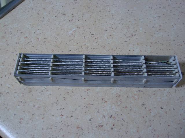
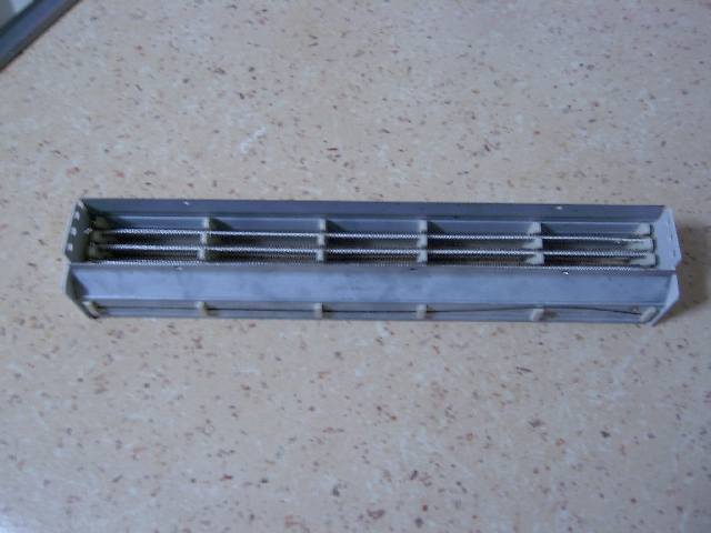
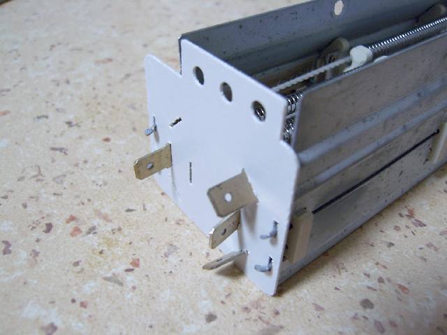
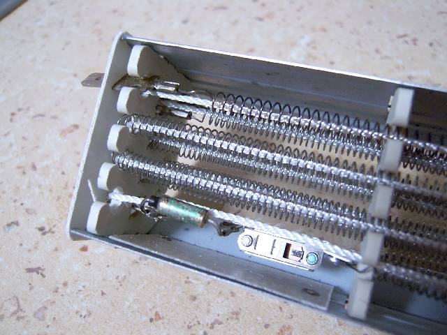
G'day all, I bought a box of these sweet little 3x 800Watt 240V heaters from Rockby Electronics. They are still $2.00ea! They will become my 48V dump load in time by shorting the ends together. This will divide the 240V value by about 5, making them just right for 48V dump voltages. I don't see why they could not be set for 12 & 24 volts as well. I even use one to load power supplies just by shifting the croc clip up and down the coils 
As the ad says, "Nickel chrome, helically wound wire supported on ceramic formers with metal frames with fibreglass supporting cores." I'm going to set them up with access to the outside air flow to allow natural cooling. You could also fan force them with some brushless computer fans. They seem to have a current and thermal fuse as well. These can be left in or bypassed. At $2 each, you can afford to break a few up for testing
Rockby 3x 800Watt 240V Heater Cores Rockby Electronics Home Page Some pics, as the Rockby listing is hard to grip: 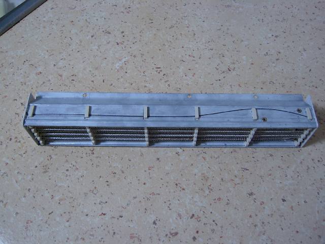
sPuDd.. It should work ...in theory |
||||
| GWatPE Senior Member Joined: 01/09/2006 Location: AustraliaPosts: 2127 |
Hi sPuDd, I make these 800W units have a 72ohm resistance. These will present about a 43W load individually on a nom 48V battery. You would probably need to modify each unit to make better use of them. A cheap find on all accounts. cheers, Gordon. become more energy aware |
||||
| sPuDd Senior Member Joined: 10/07/2007 Location: AustraliaPosts: 251 |
Yep, Just like I said: "They will become my 48V dump load in time by shorting the ends together. This will divide the 240V value by about 5, making them just right for 48V dump voltages." sPuDd..
It should work ...in theory |
||||
| GWatPE Senior Member Joined: 01/09/2006 Location: AustraliaPosts: 2127 |
Hi sPuDd, out of interest, what max power level are you expecting? become more energy aware |
||||
| sPuDd Senior Member Joined: 10/07/2007 Location: AustraliaPosts: 251 |
GWatPE, From each heater unit? About 400W-500W at least. Or the systems maximum dump load requirement? Variable from about 100W to as large as the system grows over time. sPuDd.. It should work ...in theory |
||||
| davef Guru Joined: 14/05/2006 Location: New ZealandPosts: 499 |
I need a 1KW heater element that one could put into a hot water tank. Major problem is that I only have 56 Volts to put across it. That is 17Amps, which works out to be 3.0Ohms. Any suggestions? I noticed that people are suggesting dropping some of the above mentioned dump loads into water. I can see that if the water system is grounded that getting electrocuted may not be a problem, but are there any other reasons for not placing the resistive element directly into the water? IE hydrolysis? Thanks, davef |
||||
| The Back Shed's forum code is written, and hosted, in Australia. | © JAQ Software 2026 |
