
|
|
Forum Index : Windmills : The MPPT Project.
| Author | Message | ||||
| GWatPE Senior Member Joined: 01/09/2006 Location: AustraliaPosts: 2127 |
Hi All, MPPT is progressing well. I am at final artwork stage. Screen photo is presented below. I have been unable to capture this screen, had to use camera, so apologise for poor quality. 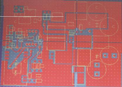
This is a multi layer board. approx dimensions are 100mm x 80mm. No heatsinks should be required. Only one picaxe is on this board. 2 other picaxe interfaces are off this main board and connect with a 4 way loom. The current sensing Hall effect device is also located OFF the board. This is designed to be a universal main board. I have also made provisions for in circuit reprogramming. I hope to have a cct in operation next week. cheers, Gordon. become more energy aware |
||||
| GWatPE Senior Member Joined: 01/09/2006 Location: AustraliaPosts: 2127 |
Hi Domwild, We must have posted at the same time. I missed your comments as the forum automatically created a 7th page link. WRT your comments. The program space for code is not a problem. The 28 & 40 pin axe micros would have enough analogue inputs. The Extra Digital I/O are not of much use here. The parallel processing ability of using multiple micro's increases the real time control ability, by sharing the tasks and prosessing the information simultanously. The MPPT is pushing the limits for the picaxe chip. I already have made an analogue control MPPT. The picaxe micro, MPPT is a project that I am tinkering with to compare performance. I am still unsure if the picaxe will process the information at a fast enough rate even with parallel processing. I had previously been unsuccessful with a single processor. A BS2 running at 20MHz, with a 4 channel A/D converter. The AXE 08M are cheap as well. I will know pretty soon, if the chips are up to it. cheers, Gordon. become more energy aware |
||||
| GWatPE Senior Member Joined: 01/09/2006 Location: AustraliaPosts: 2127 |
Hi interested readers, I have attached a photo of my prototype MPPT board. 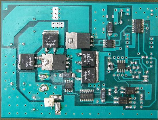
This board has the high power DC-DC converter and modulators. There is still quite a bit of code optimisation in the micro still to be done. I have had to relocate as much of the code to other micros, to improve the response time. It is inconclusive at this point to say the AXE-08M is able to perform the Maths functions necessary for correct tracking of a windmill's output power. Still some more work to do. cheers, Gordon. become more energy aware |
||||
herbnz Senior Member Joined: 18/02/2007 Location: New ZealandPosts: 258 |
Hi Gordon Any chance of sharing circuit diagrams particularly of the dc dc converter. After all I believe this is a forum where info is freely shared and built on. Herb |
||||
| GWatPE Senior Member Joined: 01/09/2006 Location: AustraliaPosts: 2127 |
Hi Herb, As you will be aware, these type of ccts do require special construction techniques. Poor construction can lead to a serious RFI problem. If this works well, there is probably economic value in it. At this point I will not be publishing any cct diags on a public forum. I may have employed similar techniques to others and I will not be publishing ccts as my own without first checking. If I have used other persons published ideas, then I intend to credit those people. I am still trying to distribute the various mathematical tasks between micros. It is pretty apparent that a single micro, AXE-08M is unable to fulfill the role by itself. The control of rapidly changing variables may still be better managed by a mixture of digital and analogue ccts. In the past I have been able to modulate at 500kHz, with a linear response 0-100%, to digitally amplify audio using a discrete component digital modulator that I have built. The digital control response time of the process usung the AXE-08M is currently a bottleneck. I will continue to press on as many DIY windmillers and solar experimenters will benefit if this technique can be successfully implimented. cheers, Gordon. 5188 become more energy aware |
||||
| herbnz Senior Member Joined: 18/02/2007 Location: New ZealandPosts: 258 |
Hi Gordon Please explain what is to be gained by this forum by the cyptic postings here. Would it not be better to only post if you are prepared to share. Let us lesser mortals get on with our primitive efforts Herb |
||||
| vasi Guru Joined: 23/03/2007 Location: RomaniaPosts: 1697 |
Hi Gordon, nice work, if you can prove  . .
What is your intention? You want to obtain a patent for your work? You have the right to do it, but ... I read this topic by email, you collected information from this forum, also you obtained high interest on this... Is this your free advertising method? The people from here don't deserve this. I will wait until the end to see what kind of man you are. I hope I am wrong, I want to be... Hobbit name: Togo Toadfoot of Frogmorton Elvish name: Mablung Miriel Beyound Arduino Lang |
||||
| Gizmo Admin Group Joined: 05/06/2004 Location: AustraliaPosts: 5182 |
Hmm. I can see where Gordon is coming from on this. Its true that these sort of inductive switching circuits do need to be well constructed or they just wont work. Although many have contributed to the knowledge base, I know Gordon has put many many hours into this project, and understandably may be reluctant to just hand it all over. But I'm sure Gordon will share some of what he has learned once the unit proves itself, and may be willing to provide a circuit of a basic MPPT module that we could develope further. Maybe a basic MPPT open source model, without all the bells and whistles of his more advanced commercial MPPT design. Hows that for diplomatic? Glenn The best time to plant a tree was twenty years ago, the second best time is right now. JAQ |
||||
| GWatPE Senior Member Joined: 01/09/2006 Location: AustraliaPosts: 2127 |
Hi Gizmo, I have intended to be cautious around this topic. I can see that even since my posting this morning that many people have an interest in this thread. Early on, different ideas did arise. This thread is now very long and it is difficult to remember all of what has gone before. I get the impression that some readers think that any Joe Bloggs with a soldering iron can replicate a cct diag into a working design. I am not prepared to have a reader attempt to build a MPPT based on a cct posted and then have it fail. The component cost is significant and I am thinking building the MPPT may go beyond the DIY scope of this forum. Herb may not be aware, but these high power switching ccts are actually substantial radio transmitters. There are rules that govern emmissions from these devices, even in New Zealand. Vasi, I will not be led into releasing info based on your comments. This topic I picked up on purely to test a theory to replicate an analogue wind MPPT that I built for, and currently have on my mill, with a digital version based on a chip that had been used successfully for other purposes by Gizmo in the past. I am sure that if a Wind MPPT was an easy task that many commercial units would already be available. I certainly would not be persuing this if I could just go and buy one. WRT your comment above. I hope to make a MPPT kit, or partially built up cct available. I will not be persuing patents etc. If this was my intention, I would have done so with my analogue MPPT design. This forum, may have some advertising value. I have not intentionally used it for that purpose. Gizmo, your diplomacy is above the line. I was not sure exactly what the response would be to me saying no. I have been trying to present findings in a methodical way, but if readers would prefer, I can continue my developments without posting updates. I am quite prepared to see the direction this thread goes without my input. cheers, Gordon become more energy aware |
||||
| RossW Guru Joined: 25/02/2006 Location: AustraliaPosts: 495 |
Gordon, your efforts in this are certainly appreciated by some at least. While some of (or much of, who knows, all of?) what you've done may have been already done in part or in whole by others, the *PRACTICAL* distillation of that work is not readily available to "us". I also must say, that as somene who has been laying out PCBs, designing circuits and writing software for a living since the late 1970s - I appreciate the difficulty in effectively translating a schematic into a working product. If you do go forward with this and end up with a functioning system capable of working in the 1KW-1.5KW area at 48V nominal system voltage, and can do so in either a short-form kit or something substantially similar, I'd like you to take this as an official "expression of interest" to purchase one. I've been planning to build my own, but the time constraints of all the other things I find myself needing (as opposed to wanting) to do make it impossible in the forseeable future. Good onya mate, hang in there. R. |
||||
| vasi Guru Joined: 23/03/2007 Location: RomaniaPosts: 1697 |
I keep my mouth quiet because I have respect to Glenn. I will try to see if I can send you an email (a civilized one). BTW, the same PIC chip (not PICAXE prepared) don't have the same real time problems. And is easy to program in JAL language. Hobbit name: Togo Toadfoot of Frogmorton Elvish name: Mablung Miriel Beyound Arduino Lang |
||||
| commanda Newbie Joined: 12/11/2007 Location: AustraliaPosts: 14 |
For those that are interested in running the F&P in high voltage mode with a buck converter, I present the following link as food for thought. http://www.qrp4u.de/docs/en/smps_new/ You can feed a dc control voltage into pin 2 of the SG3525 (via a series resistor) to vary the output voltage, and hence the current into the battery. Amanda |
||||
| herbnz Senior Member Joined: 18/02/2007 Location: New ZealandPosts: 258 |
Hi Amanda I have been working with this info and have gathered up parts just need some spare time . I have not mentioned my progress here as it was given the thumbs down to use this type cct as quoted above Herb |
||||
| commanda Newbie Joined: 12/11/2007 Location: AustraliaPosts: 14 |
I presented that particular circuit because, with the synchronous rectification and fet drivers, it is considerably more efficient than your average pc psu. Personally, I'm on the verge of withdrawing from this forum alltogether. I was under the impression this thread was all about a group of enthusiasts working together and pooling expertise and knowledge to develop an open-source hardware and or software solution to the DIY windmill MPPT. Unfortunately, it appears to have degenerated into a one-man show (not that he has any intention of actually showing anything, because the rest of us wouldn't be smart enough to copy his work and make it work), and he has grand designs on selling the thing. GIZMO, fell free to kill off my account here any time you choose. I'm about to lose it completely and tell a certain wanker what a wanker he really is. Amanda |
||||
| The Back Shed's forum code is written, and hosted, in Australia. | © JAQ Software 2026 |
