
|
|
Forum Index : Windmills : DOUBLING FISHER an PAYKEL OUTPUT
| Author | Message | ||||
| KiwiJohn Guru Joined: 01/12/2005 Location: New ZealandPosts: 691 |
Yes, thats right Herb and that is why Lz and Cz will be equal at one frequency and at that point voltage and current will be in phase and the circuit will be in tune. |
||||
| Gizmo Admin Group Joined: 05/06/2004 Location: AustraliaPosts: 5182 |
Thats very good work Herb, some real figures. Now that we know there is a loss in efficiency and we need to put more power in to get the power out, we can go foward with this. It means bigger blades to get more power, but like Dennis said it also means a lower startup RPM and better low speed performance. Next question is what sort of caps "should" we be using for this. Are the fluro caps OK, or should we use motor start caps. I know fluro caps work, but thse caps can get hot and explode if not used correctly. Glenn The best time to plant a tree was twenty years ago, the second best time is right now. JAQ |
||||
herbnz Senior Member Joined: 18/02/2007 Location: New ZealandPosts: 258 |
Hi Glen Dont use motor starts these only rated for start. flour ones ok power factor ones from three phase motors also there are 10 mfd ones in some FP controlers. dont cut any old caps open there are still some out there that contain pcb's At the moment i see it as easier to change windings than switch caps but it is another avenue for us . I will try to look at effects of a fixed value cap as the rpm goes up while i am setup Herb |
||||
| KiwiJohn Guru Joined: 01/12/2005 Location: New ZealandPosts: 691 |
Herb, I expect that having fixed value caps in the system will cause a peak in output around the frequency (i.e. rpm) where the inductive and capacitive reactances are cancelling each other. I also expect that some capacitance will always be better than none at the rpm ranges we are interested in. Just a hunch really.  |
||||
| FandPwithPVC Regular Member Joined: 09/09/2006 Location: Posts: 64 |
Hi All I don,t agree that F and P generators are 95% efficient. Far from it is probably closer to 50%. Despite the New Zealand charts the 80 SP in star is not the best one. On a 24 volt system the chart suggests a speed of 260 RPM but it is more like 300 RPM . All the potential output under 300 RPM is wasted. Adding three lots of 216 uF caps brings this speed way down to 216/220 RPM, (80 RPM ) The F and P we now use is a 100S Modified Rewire. It is much simpler to rewire putting out at 216/220 RPM and with better output than the 80SP at the top end. Questions on what sort of caps to use and how have already been answered several times. Our dealings with 100s of caps showed that if you know what you are doing there are no problems but don,t use the ones off the F and P boards. All the cap testing for 24 volt systems has been completed. All for Now Dennis L |
||||
| Gizmo Admin Group Joined: 05/06/2004 Location: AustraliaPosts: 5182 |

Herb has show the F&P to be closer to 82% efficient in his testing. The question of capacitor type is raised because caps, unlike stators or rectifiers, can explode if the wrong type is used. So I'm seaking the best advise from anyone who may know what sort of cap is safe to use for this application. I dont know the safe operating conditions for fluro or motor start caps, and I wont take a guess in case someone gets hurt, so I asked the question about which AC non polarized cap should be used and what types should be avoided. A typical AC cap like the fluro caps are designed to run at 50Hz, but on a F&P this could be several hundred Hz, and the cap may get hot as a result. Thanks Herb for the answer. I DO know the big 330uF 250V caps on the F&P controller board are not suitable because these are polarized electrolytic caps, DC current only. These WILL explode if used in a AC circuit, like on our F&P stator. They can be used if they are connected back to back with a couple of diodes, but this gets tricky for average Jo and is a little dangerous. Another thing, everyone playing around with this please be carefull, the F&P can easily make enough volts to kill you when not connected to a safe low battery voltage. Glenn The best time to plant a tree was twenty years ago, the second best time is right now. JAQ |
||||
| GWatPE Senior Member Joined: 01/09/2006 Location: AustraliaPosts: 2127 |
Hi Glenn, Any cap that is non polarized with a rating of 415VAC can be used. As others have stated a motor start cap will be physically smaller for the same capacitance. These caps are not rated for continuous use and will leak, or explode. Generally, the higher the voltage rating the better. The type can be metalized polyester, paper, polypropylene. Generally a lot of smaller caps will dissipate heat better than a single cap of the same value and voltage. If you use second hand caps you may find you include caps that do not meet the printed specs on them. These will probably get hot and explode. The caps will usually fail if the mill is at max rating or unloaded suddenly at peak power. Caps are difficult to test. Meters are around that can measure a cap impedance. Low impedqance means less heating, higher efficiency and better smoothing with higher peak currents. The caps should be the same type and rating if possible. I would not even bother to make use of polarized caps using diodes. It would be advisable top include some sort of bleed resistor directly across each cap bank[100k]. This will reduce the risk of electrocution should the cap be disconnected at the AC peak voltage. I hope this helps. cheers, Gordon become more energy aware |
||||
| Tinker Guru Joined: 07/11/2007 Location: AustraliaPosts: 1904 |
While on the topic of capacitors, nobody has yet mentioned that they ought to be connected by as short a wire as possible to the stator coils. Having a 'capacitor bank' located somewhere remotely entails heavy and rapidly reversing charging currents trying to heat up lenghty wires and possibly negating the capacitive effect to a large degree. Anyway, that's the way I see it, others may disagree and will no doubt tell me so 
Klaus |
||||
| herbnz Senior Member Joined: 18/02/2007 Location: New ZealandPosts: 258 |
Hi I Agree Gordon. I must clarify when i refered to using caps of FP boards i was refering to a non polarised type rated 350 volt ac working, connected where the mains power comes in. any that show + or - dont use. Also never expose skin etc to liquids inside damaged units pcb's used in old units cause cancer big time most recalled in Nz and Oz but many not picked up I agree Denis re figures graphs published in NZ are not accurate one other member commented in a different topic a suitable use for them. Tinker that is so right also reason rectfier needs to be near the stator only Dc comming down the battery cable Herb |
||||
| herbnz Senior Member Joined: 18/02/2007 Location: New ZealandPosts: 258 |
Hi I have struck a snag testing at higher revs 500 rpm reguired to much power from the drill i use to drive the lathe to get variable speed. Have another 1kw dc motor but at the moment we are becomming short power hydro's drying up windmill crapped out solar good. I did get readings for 500 rpm without caps input power = 323 watts (2.1 kgf ) outpot power = 229 (27v 8.5a ) eff =71% Putting the caps in was like hitting a brick wall I will need a lot more drive power on the lathe. I have included a photo of my setup its very simple I was wondering if someone with a grid connection could setup > This area needs a lot of investigation. I did transfer the caps to my small hydro unit with very interesting results I will document under a separate topic soon. Has anyone that is using caps on windmills struck any unusal mechanical breakages ? 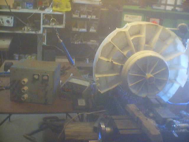
Herb |
||||
| KiwiJohn Guru Joined: 01/12/2005 Location: New ZealandPosts: 691 |
[quote]Putting the caps in was like hitting a brick wall I will need a lot more drive power on the lathe. [/quote] This is very curious Herb, are you saying the genny was so much harder to turn just with caps on and no load? However, if you are saying the genny was so much harder to turn with the same resistance load then that is to be expected as you would be producing so much more output. |
||||
| herbnz Senior Member Joined: 18/02/2007 Location: New ZealandPosts: 258 |
With load batteries connected all testing yeah expected but i never had enough in put power Increase is quite large tho Herb |
||||
| Gizmo Admin Group Joined: 05/06/2004 Location: AustraliaPosts: 5182 |
Has anyone tried testing without a load? With all this LC ringing going on I wonder what the load is like, without a load connected, if you get my meaning. Would also be interresting to see what the peak voltage is with no load, if it goes above the save operating levels of the caps or rectifier. I really wish I had a lath capable of spinning a F&P. Glen The best time to plant a tree was twenty years ago, the second best time is right now. JAQ |
||||
| GWatPE Senior Member Joined: 01/09/2006 Location: AustraliaPosts: 2127 |
Hi Herb, Some definite experimental data to validate my conclusion on another post. If the mill is closely matched to the load, then adding caps will probably require a change to the blades to drive the mill. The caps lower the rpm at which the mill generates enough volts to start charging the batterey. Remember though that if the battery is down in volts, then it will present a biggeer load to the mill as well. The caps work best on a mill that usually puts out late, and would be considered to be underloaded, or [overdriven]. The theory suggests that without changing the blades or the load, that a mill output current can only be increased when the caps increase the efficiency of the energy transfer from the wind to the battery. To double the power output would suggest that the blade and generator combination work better with the caps added for a mill that is under loaded prior to adding caps. The caps do not double the efficiency of the generator by itself. As you have measured, a mill that is well matched to the load suffers a decrease in performance when caps are added as the blade will tend to become stalled by the apparent extra load. Adding caps to a poorly matched system can increase the system current output, where there is basically an excess of generating capacity that was not previously able to be utilized. As Dennis has stated, if the caps cost next to nothing and you measure increased current then it is worthwhile. If you don't get an increase then it shows your system was pretty well matched. This will probably add to the confusion. cheers, Gordon. become more energy aware |
||||
| herbnz Senior Member Joined: 18/02/2007 Location: New ZealandPosts: 258 |
A lot testing is needed yet to determine the loss or gain in eff of this method. I have posted my hydro experiance on other stuff . so this forum stays on windmills although hydro is where i learn most about FP. Glen with your ability it would I think be no problem to setup a frame with a motor driving a FP that is mounted to have limited movement in its mountings. I will try and sketch something up it is my intention now to do this with my larger drive motor so i can leave set up Herb |
||||
| FandPwithPVC Regular Member Joined: 09/09/2006 Location: Posts: 64 |
Hello All Herb You have connected your phases incorrectly or got your rewind wrong . We have also done this. A question. What are "start flour ones" Is this something to do with food ? Regards Dennis L |
||||
Highlander Senior Member Joined: 03/10/2006 Location: AustraliaPosts: 266 |
G'day Dennis, well done mate. These little FP's are starting to get somewhere. I'm sure Herb meant flouro ones (caps) I might try these myself. I'm too lazy to scrounge up and wire all those caps, I might see if there are any bigger ones at dse or jaycar. Can you suggest a uf value for the 7 phase? Thanks Mark Central Victorian highlands |
||||
| herbnz Senior Member Joined: 18/02/2007 Location: New ZealandPosts: 258 |
Hi What makes you think I have made incorrect connections ? Maybe you could make you test results available so we can see where we differ. The stator is off my Ecoinnovation windmill that has until recently been up and running.Personally on the hydro units I manufacture I dont reconnect stators I find it easier, faster and more flexible to rewind (ie this stator's equivalent is 16 turns/coil). I realised to obtain results that were comparable I needed to use what is in common use. Having also worked with three phase motors, generators etc for 35 years it is a matter of habit to fully test outputs to ensure correct connections and phase balance. Many thanks for highlighting my typo I have been trying to put the u before o in fluorescence for many a year. Hi Highlander you will be next to get corrected you followed my mistake. If you go to a Electrical outlet that handles electric motors or a motor rewinder they will have a source of power facter correction caps of larger values cost could be scary tho but not bad DSE or Jaycars Herb |
||||
| FandPwithPVC Regular Member Joined: 09/09/2006 Location: Posts: 64 |
Hi All We have done dozens of rewinds and are probably nearing a hundred or so.In doing rewinds we sometimes get it wrong especially when a new player is involved or a more complicated rewire is attempted. On our test bench our 240 Volt motor refuses to start at times and this could be said to be our BRICK WALL .It appears that in hydro situations higher speeds with less torque are sometimes involved Windmills are such that in most if not all cases 500 RPM is very fast. Therefore 150rpm to 400rpm could be considered as the best operating speed. In a past reply we stated that a 100SP Modified was the best but it isnt. I will open up a new post 80 SP in Star with these results. It is asked that only people who have towers up with F and Ps or test benches similarly set up reply. It gets very confusing with the THEORY GENIUSES WAITING TO JUMP IN Regards Dennis L |
||||
| The Back Shed's forum code is written, and hosted, in Australia. | © JAQ Software 2026 |
