| Author |
Message |
KiwiJohn
Guru

Joined: 01/12/2005
Location: New ZealandPosts: 691 |
| Posted: 07:54am 25 Oct 2007 |
 Copy link to clipboard Copy link to clipboard |
 Print this post |
|
I dont think this is really new to our discussion but it is a different way of looking at the same thing.
We have talked about an MPPT to adjust the load and to continuously seek the maximum power output and we have discussed the significance of relative wind to the efficiency of the turbine. Lets look at this relative wind aspect again. Relative wind is the angle the air flow makes to the leading edge of the turbine blades.
Relative wind can be calculated if we know the RPM and the wind speed. The RPM is easy to determine as it is directly indicated by the frequency of the AC output from our alternator. For wind speed we need an anemometer.
Put these two values together (RPM and knots) and we can calculate the relative wind.
When the turbine is overloaded the RPM will drop and the relative wind will change one way, when the wind picks up the relative wind will change the other way and turbine will tend to over rev because it is under loaded. I suggest that by adjusting the load the relative wind can be kept within an optimum range and this will correspond with best turbine efficiency.
So, put the two inputs (wind speed and turbine RPM) together and adjust the duty cycle of a PWM to keep the combination, and hence the relative wind, within the optimum range.
Hopefully, there will be times when the mill is producing more than can be usefully used and that is when a dump load would start to soak up the excess. Around about then auto furling would start to come into play.
Edited by KiwiJohn 2007-10-26 |
| |
Gill

Senior Member

Joined: 11/11/2006
Location: AustraliaPosts: 669 |
| Posted: 11:33am 25 Oct 2007 |
Copy link to clipboard |
Print this post |
|
John,
I don't think you have a valid approach there. It is for the very reason I advocate a variable pitch prop instead of a fixed pitch.
With our fixed pitch we have a fixed design TSR which is linear to wind speed and RPM.
Perhaps we confuse tracking of which maximum power point?
Do we not have the the winds blowing power, the shafts rotational power, and the generators electrical power, and the batteries charging power demand?
Now the conversion of wind power into shaft power is carried out by the prop. Conversion of shaft rotational power to electrical power is carried out by the generator. Is not the task of the MPPT to better match the generators power to the needs of the battery?
Sure they are all come from the same source up the chain, but the further up the chain we go the more variables we introduce. We have already identified response time as one such variable and Core saturation another.
Surely the better device will avoid these accumulating variables by metering immediately where the conversion is being done. And as I see it it is "generator power available" as the in and "battery power demand" as the out.
Yes I suppose it could be made to work on one machine, but I would prefer a circuit that could be fitted to any machine.
was working fine... til the smoke got out.
Cheers Gill _Cairns, FNQ |
| |
herbnz

Senior Member
Joined: 18/02/2007
Location: New ZealandPosts: 258 |
| Posted: 02:55pm 25 Oct 2007 |
Copy link to clipboard |
Print this post |
|
Hi
Gill Stated "identified response time as one such variable and Core saturation another."
The only time the core is saturated in a FP is at no or low current flows.
I think Gill you are refering to current limit caused by mmf stator =(nearly) mmf rotor.
At this point stator carries very little flux
HerbEdited by herbnz 2007-10-27 |
| |
KiwiJohn
Guru
Joined: 01/12/2005
Location: New ZealandPosts: 691 |
| Posted: 08:17pm 25 Oct 2007 |
Copy link to clipboard |
Print this post |
|
I am sorry Gill, I know you mean well but you cant discourage me that easily! 
So here are my slightly refined thoughts on the matter. 
I agree wholeheartedly that a variable pitch prop is an excellent way to go but unfortunately it is beyond the means of most of us. 
The combination of wind speed and RPM is of course exactly what TSR is and as you so rightly point out a fixed pitch prop has a fixed optimum TSR.
However, I am thinking that the combination of wind and mill etc is rarely constant and that the wind varies considerably (at least around here!) from moment to moment.
This is not to knock the MPPT approach but if I understand it correctly anything that works by monitoring the output of the mill is reacting to changes in the combination of wind, turbine (i.e. the 'prop'), generator and load whereas what is really changing is the wind speed and I am seeking practical ways to adjust the mill to take advantage of wind changes as they occur, not some time later.
In the absence of any practical means to adjust the pitch of the blades it appears adjusting the load is about the only variable we can tweak in real time.
Suppose we have our mill in a nice mild breeze and it is operating comfortably at it's TSR of 7. Now the wind begins to pick up and the TSR falls, the load is the same but the wind is stronger and the output will not increase until inertia allows the mill to speed up. However the mill is on its 'back foot' having fallen out of it's efficient band and the blades are tending towards stalling. If the gust is short duration the mill might hardly speed up at all and the extra energy of the gust has been missed.
Consider though that we had a means of quickly detecting the gust (i.e. an anemometer) and by our simple calculation of wind speed and RPM we will detect that the mill was at that moment operating below the speed for optimum TSR. So we REDUCE the load! Freed of the load the mill (more) quickly accelerates to regain optimum TSR at which point we put the load back on to take full advantage of the increased wind. In the case of a short gust the mill would be found to be spinning faster than optimum TSR at which point we INCREASE the load and so extract the energy of the gust from the inertia of the mill.
a = RPM x Circumference of turbine
b = wind speed
TSR = a / b
When TSR is greater than optimum reduce 'a' by reducing RPM by increasing load.
When TSR is less than optimum increase 'a' by allowing RPM to increase by decreasing load.
Well, thats my thoughts anyway! 
Edited by KiwiJohn 2007-10-27 |
| |
GWatPE
Senior Member
Joined: 01/09/2006
Location: AustraliaPosts: 2127 |
| Posted: 11:55pm 26 Oct 2007 |
Copy link to clipboard |
Print this post |
|
Hi KiwiJohn and Gill,
some interesting reading.
KiwiJohn has summed up the real world scenario well. We have to keep mill inertia to a minimum
Inertia increases with blade numbers. unfortunately F&P needs a certain blade area to start turning. increasing blade dia reduces rpm. Inertia on a F&P mill will be high due to mechanical constraints.
I posted a graph showing the measured response of my mill to wind. 10 Samples/sec rate. A mill under load can repond quickly to wind gusts.
Once the rotor is turning and unloaded the rpm is greater than the optimum TSR. At this point the mill can be loaded. If the rpm changes with wind speed and the TSR goes above and below optimum this does not seem to affect mill output too much. Wind energy is stored as mill inertia above this optimum and extracted below it. As long as overloading or underloading is not severe, efficient energy capture occurs. The most importand aspect to consider is to not overload the rotor at the beginning of a wind gust.
I will clarify what my MPPT does.
My MPPT loads my mill in a response to the rotor rpm. As the wind speeds up the blade rpm increases. The load is then increased and more power extracted. The rpm follows the wind speed. current increases with a squared relationship and the voltage a linear relationship with increasing wind speed. This is a pseudo cubic power relationship. I have not evaluated the transfer equations for each section of the electronics.
As long as the rotor increases rpm linearly with increasing wind speed the TSR will probably remain close to optimum. I have achieved this using 2 controls on the same modulator without any feedback.
I only need to monitor generator rpm.
All mills will have a similar characteristic. The only problem a mill with an iron core has is that as the rpm increases, iron hysterysis loss increases. This however only becomes significant above 600 rpm.
A variable pitch control would be useful as the startup problem could be reduced. I have concerns about useful lifetime and mechanical servicing of this type of control though.
I think most would agree that if TSR was so critical that none of us would get much power from our mill as the mill would only be efficient at one particular rpm. This does not happen. A blade can work well over a wide operating speed range. We really need to look at the areas that the combinations don't work well.
cheers, Gordon.
become more energy aware |
| |
Gill
Senior Member
Joined: 11/11/2006
Location: AustraliaPosts: 669 |
| Posted: 02:02am 27 Oct 2007 |
Copy link to clipboard |
Print this post |
|
I see this is more a robbing Peter to pay Paul exercise, whereas I feel to get efficiency to approach Betz or as a wild dream to pass it, the efficiency of each building block needs to be addressed and peaked individually.
Well that's my approach but as indicated our modern 'reality' needs the quick fix.
So rather than allow my constructive criticism to become a negative influence, I'll shut up now allowing you to pursue the subject further. I'll still participate if I may should I have positive input toward your goal.
was working fine... til the smoke got out.
Cheers Gill _Cairns, FNQ |
| |
KiwiJohn
Guru
Joined: 01/12/2005
Location: New ZealandPosts: 691 |
| Posted: 02:56am 27 Oct 2007 |
Copy link to clipboard |
Print this post |
|
I see the potential advantage of reacting to a change of wind speed (which could be detected by change of relative wind or by an anemometer) rather than a change of shaft speed is that reacting to the wind directly puts us one step ahead of the delay induced by inertia.
If our mill is to be a good 'gust catcher' it must react quickly to rising wind. As you so rightly said Gordon "The most important aspect to consider is to not overload the rotor at the beginning of a wind gust." I am pleased that we agree on this as in one of my posts I said that when the wind increases suddenly the reaction should be to REDUCE the load so allowing the rotor to more quickly spin up to the new optimum speed.
The difference I see between us is that I am promposing reacting to wind changes whereas your method of control reacts to the turbine's reaction to the wind change.
To think if it another way, if you are driving your car is it better to change down when you see the hill ahead or to not change until climbing the hill causes your engine revs to drop?
No argument there Gill, the efficiency of each building block should indeed be addressed and peaked individually which is all the more reason to react to the wind, not its effect on one or more of those building blocks. Personally, I always see your input as positive. |
| |
GWatPE
Senior Member
Joined: 01/09/2006
Location: AustraliaPosts: 2127 |
| Posted: 03:13am 27 Oct 2007 |
Copy link to clipboard |
Print this post |
|
Hi Gill,
Didn't Betz imply that the max power that can be extracted is around 60%. If you try and get more, then the air will tend to flow around the mill blades, rather than through them.
I guess that the issue is that all of the variables are interrelated. It is not the purpose of this discussion to delve into fourier transform analysis or solving differential equations.
I will continue with the electonics. I should be able to post some data in a couple of weeks.
I do not think there is a quick fix. I have been working on my system for years. I am looking at a micro controlled MPPT to extract more power from an existing mill in the same wind.
I will have to think some more about points raised.
There is probably another aspect to consider.
cheers, Gordon.
become more energy aware |
| |
GWatPE
Senior Member
Joined: 01/09/2006
Location: AustraliaPosts: 2127 |
| Posted: 11:37pm 28 Oct 2007 |
Copy link to clipboard |
Print this post |
|
We have had a real blow, the last few days.
+100kph on the Saturday.
I was able to get some more comparison data.
My mill without MPPT is similar in characteristics to an 80SP. Will only charge a battery at higher rpm.
What I have experimentally determined is that a mill without a MPPT does respond faster to wind gusts, and in gusty conditions the maximum power output is greater than with a MPPT. This is primarily a result of the lag of the rotor caused by the mill being loaded more at the bottom end by the MPPT. Without a MPPT there would be no output at this rpm though. If the wind was sustained then the output would plateau to be the same at the top end for both conditions.
The benefit of the MPPT is that the average power is increased.
If the wind speed was measured independently and this was used as the controlling variable then a faster response time would occur. I am thinking of adding an anemometer for this purpose for comparison.
My initial KISS principle dictated using only the generator voltage. Measured diffference between MPPT ON and OFF is < 5% in measured maximum output power, but average output power increased 40% with MPPTing. These results are subjective, because real wind was used to drive the mill.
A wind tunnel testing would produce more objective results for comparison.
The mill without MPPT exhibits < 0.5 seconds lag to the wind gust. I measured gusts occurring within a 4 second window.
Do any readers offer other suggestions to adressing the problems associated with controlling mechanical systems with these short response times.
I expect that some readers will now be aware that the MPPT can only be if the actual power in the wind at that instant is measured and controls the mill directly.
Any other solution including mine can only be called something else unless this is done.
I will continue with an electronic approach, but I hope discussion continues with other solutions.
cheers, Gordon.
become more energy aware |
| |
KiwiJohn
Guru
Joined: 01/12/2005
Location: New ZealandPosts: 691 |
| Posted: 01:05am 29 Oct 2007 |
Copy link to clipboard |
Print this post |
|
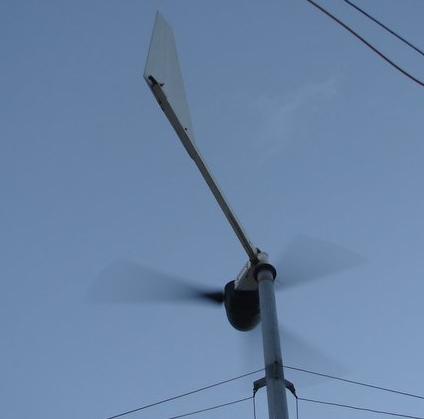
I suggest that a fast acting anemometer is required if we are to get the most advantage from measuring the wind speed directly. There does not seem to have been any comments on my sonic anemometer, (perhaps with good reason ) however an effective and easy to make anemometer can consist of a simple vane on a horizontal pivot mounted so that the wind blows the van and operates a variable resistance, along the principles of the fuel level sendor fitted to very many vehicles.
Mounting the anemometer leads to a whole new set of questions. I am assuming that it should not be behind the turbine blades leaving either outside the blade circle or in front of the blades. In front of the blades might be tricky! Maybe on a pole up above the blades is the appropriate place? |
| |
GWatPE
Senior Member
Joined: 01/09/2006
Location: AustraliaPosts: 2127 |
| Posted: 03:01am 29 Oct 2007 |
Copy link to clipboard |
Print this post |
|
Hi KiwiJohn,
I think the mounting position is paramount. I chose to use mill generated output volts as I did not want to complicate the tower slip ring assembly.
I did look at getting an output from my DAVIS weather station, but it fell into the too hard basket. I might look at a cheap weather station cup anemometer with a reed switch or hall effect pulse output and convert this to a proportional voltage linear with windspeed.
Direct conversion of pulses per second with a charge pump is highly non linear. I will look at the counter function of the picaxe and maybe make a dedicated unit using a cheap cup anemometer. The picaxe can count pulses up to a frequency of 25kHz. Would need 2000 pulses per second at say 30 kph to get max resolution of PWM output. The sampling rate would have to be around 10Samples/sec.
This has to be a dedicated unit, so cannot use Gizmo's code here.
I think that mounting on a side bracket to the tower below the rotor would still be OK for most people.
cheers for now, Gordon.
become more energy aware |
| |
KiwiJohn
Guru
Joined: 01/12/2005
Location: New ZealandPosts: 691 |
| Posted: 05:09am 29 Oct 2007 |
Copy link to clipboard |
Print this post |
|
Hi Gordon
Mounting the anemometer on the tower means it has to be a omni-direction device, maybe a drag cup or such like. But if it is mounted on the mill itself the anemometer could be more simple including the vane and potentiometer types, real easy to read the output of that!
cheers |
| |
GWatPE
Senior Member
Joined: 01/09/2006
Location: AustraliaPosts: 2127 |
| Posted: 05:53am 29 Oct 2007 |
Copy link to clipboard |
Print this post |
|
Hi KiwiJohn,
I have a real problem with something actually mounted on the mill.
Wireless? Additional sliprings? Wash from the rotor? Power supply?
I am currently looking at a breakout box from my DAVIS cup anemometer. I have finished code for a picaxe, so hopefully will have some data to record soon.
cheers, Gordon.
become more energy aware |
| |
adelaide
Regular Member

Joined: 24/03/2006
Location: AustraliaPosts: 46 |
| Posted: 06:11am 29 Oct 2007 |
Copy link to clipboard |
Print this post |
|
just a long shot but could a pic calqulate load(wats out) and timeing of ac pulses (of f ps ac coil )to do that for you .ac pulses getting shorter with hi load incress etc if watts out taken into acount i sepose you can get a better anmomter than the prop itslf / fine timing thow to work ?
help to make progres or radio and vitamin b |
| |
KiwiJohn
Guru
Joined: 01/12/2005
Location: New ZealandPosts: 691 |
| Posted: 07:01am 29 Oct 2007 |
Copy link to clipboard |
Print this post |
|
Gordon,
what I had in mind was a pole sticking up above the rotor disk with the anemometer on there.
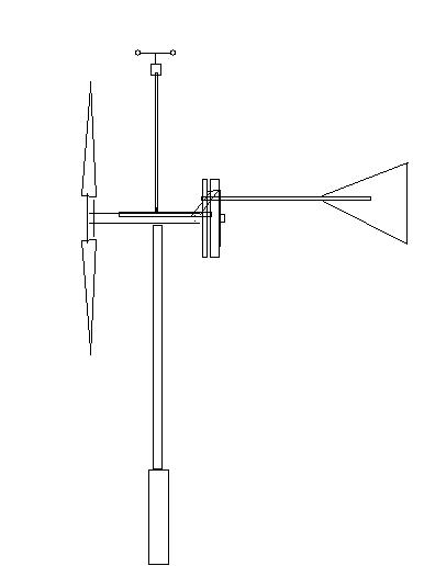 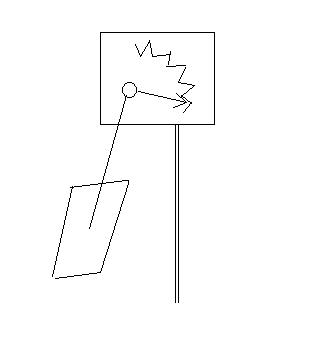
The second diagram is of course the very simple vane and potentiometer anemometer. If it is not mounted on the mill it would of course need its own directional vane to keep it into wind. |
| |
GWatPE
Senior Member
Joined: 01/09/2006
Location: AustraliaPosts: 2127 |
| Posted: 08:42am 29 Oct 2007 |
Copy link to clipboard |
Print this post |
|
Hi KiwiJohn,
the left diag would require a hollow shaft for the yaw box if I am not mistaken.
I am sure the vane would have a very non linear response.
I have checked the DAVIS cup anemometer and the output is not usable either.
I may resort to a heath robinson design using a bearing assembly from an old hard disk.
cheers Gordon.
become more energy aware |
| |
Gill
Senior Member
Joined: 11/11/2006
Location: AustraliaPosts: 669 |
| Posted: 12:27pm 29 Oct 2007 |
Copy link to clipboard |
Print this post |
|
G'day adelaide,
The answer is yes the PICAXE can measure watts(be it volts and amps then multiply these to give watts) and also it can count the AC cycles of one of the phases.
Unfortunately this only indicates the current RPM of the generator, whereas an anemometer gives the current wind speed even though the generator has not yet wound up to the corresponding RPM yet. By working off the wind the idea is to increase or decrease the electrical loading in advance/as it happens so that it stays at the highest possible RPM in spite of wind(power) changes.
I think Gordon's current old system worked off the RPM so you were not to far off the mark at all. 
was working fine... til the smoke got out.
Cheers Gill _Cairns, FNQ |
| |
GWatPE
Senior Member
Joined: 01/09/2006
Location: AustraliaPosts: 2127 |
| Posted: 01:48pm 29 Oct 2007 |
Copy link to clipboard |
Print this post |
|
Hi All,
The theory predicts that in any control that involves a time lag, the output will always chase the set point. If feed forward is employed then this will be prone to oscillation as there will be predictive overshoot which will cause oscillation.
My observations with wind gusts shows a very rapid change in windspeed from increasing to decreasing velocity in the maximum windspeed area of a wind gust. Any control dampening tends to increase the response time and compound the problem.
We will probably have to accept that the true maximumum power point will not be achieved with any system.
I can accept that my cct may be improved slightly at the top end of the power range, but a similar effect could be obtained by increasing the windspeed that furling occurs.
Even though I have measured 455W mill output, I have detuned the top end to restrict power output to just over 400W.
I think reliability has the edge over maximum power anyway.
I still maintain that most of us would just want the mill to produce power to our battery etc as long as it is turning. It is frustrating when we see the mill spinning but no output amps, or just spurts of current during gusts, or the mill never really seems to get going.
I have found that a good indication that a mill is loaded correctly is when in gusty conditions and the mill is furling; - If the rotor swings back past being face on to the wind then the mill is not loaded enough. If the mill furls and then comes back slightly, then the mill is overloaded. If the mill furls and then just returns to face on to the wind following a gust, then the mill is pretty well loaded.
Others may have views on these observations as well.
This MPPT discussion will prevail long after we think we have a solution.
cheers for now, Gordon.
become more energy aware |
| |
