
|
|
Forum Index : Windmills : 7 phase F&P works first time
| Author | Message | ||||
| GWatPE Senior Member Joined: 01/09/2006 Location: AustraliaPosts: 2127 |
Hi Gill, are you saying that with the F&P stator, if you had a comparison rig turning at say 500rpm. If you had 2 idintical winding units say 1mm wire, on the same shaft, assume unloaded. machine 1 was wired in star with rectifier on each phase. machine 2 was Jerry rigged with separate rectifier on each phase. What relative DC voltage would the Jerry rigged machine have compared to the normal rectified star machine. I think we may be commenting on different things here. I have re read your post and I think you mean recombining the separately rectified windings back in a star configuration. I am trying to visualize this. I think this is the same as what tinker was talking about with the landcruiser alternator. I have since found a thread on fieldlines that discusses the Jerry rig. There was another post where the 1.7 factor was brought up. There was an explanation about phase difference between windings and these 2 windings being in series in star that makes the output voltage less than double. I had a look at that link above also, but there were too many photos. I cannot think where this thread is going now. cheers, Gordon. become more energy aware |
||||
| Tinker Guru Joined: 07/11/2007 Location: AustraliaPosts: 1904 |
Here is a scanned picture (of the correct size I hope  ) of the alternator's star point diodes I mentioned earlier to show what I was asking: ) of the alternator's star point diodes I mentioned earlier to show what I was asking: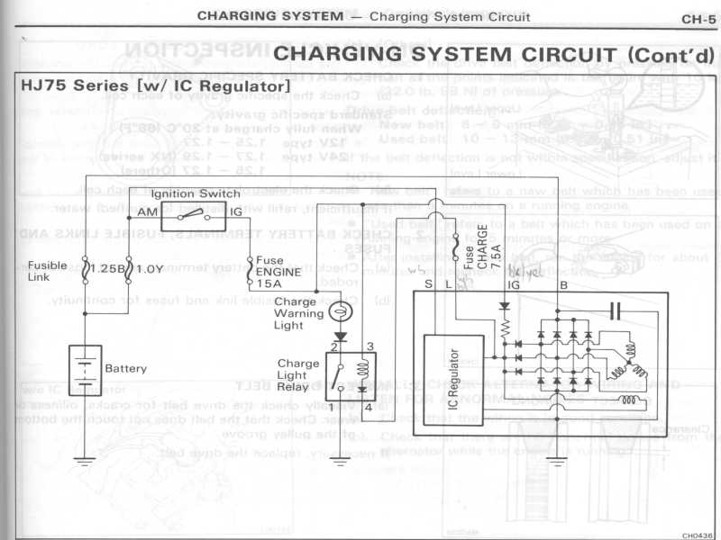
Thanks to all who posted the interesting comments on this subject above. Klaus Klaus |
||||
| GWatPE Senior Member Joined: 01/09/2006 Location: AustraliaPosts: 2127 |
Well done Klaus, I think my cube description was pretty accurate. I would include the extra diodes, but the current rating may be hard to calculate. cheers, Gordon. become more energy aware |
||||
herbnz Senior Member Joined: 18/02/2007 Location: New ZealandPosts: 258 |
Hi All I have mentioned this connection in relation to changing delta to star. using indepentant then shorting one side windings gives star leaving diodes in means change can occur with only two NO contacts. The advantage diodes in star point is they balence windings if any mismatch in phases current will be very small. On my test rig I have never detected any current in the star point with the FP stator windings but if a phase is lost it will give back up to some degree. By the way Gill when I presented this before it was only your comments that stated it was half wave it is full wave both delta and star. Also another point putting indepentant in series will not give double but root 3 out due to phase shift. unless you have filter capacitors. Herb |
||||
Gill Senior Member Joined: 11/11/2006 Location: AustraliaPosts: 669 |
G'day all, Gordon, I cannot comment on the FieldLines' Jerry rig, beyound what I have already said, as like Gizmo, I could not find an adaquate description let alone a sample circuit of what they were on about. Indicators were that it was the same I refer to as 'Inde', but I am not sure. If you have definately worked out what it is, how about a picture so we can compare? Herb, Glad you too disagree with double for the IndeS. Thanks for jogging the memory on the Star/Delta switching. Yes, I still don't grasp the results you reported there. Perhaps I should take another look at it one day soon. was working fine... til the smoke got out. Cheers Gill _Cairns, FNQ |
||||
| KiwiJohn Guru Joined: 01/12/2005 Location: New ZealandPosts: 691 |
Hmmmm... I cant see anything very magical in the vehicle circuit posted by Tinker, it is fairly conventional full wave rectified star connected as far as I can see. What is a little curious is the half wave rectified supply for the field coil. |
||||
| KiwiJohn Guru Joined: 01/12/2005 Location: New ZealandPosts: 691 |
If I add a number of sine waves, of regular phase displacement, will the sum not be a sine wave? I think we did this many months ago when we were looking at multiple phases as a means to ease starting. Later: Here is the topic I was thinking of sine waves etc |
||||
| herbnz Senior Member Joined: 18/02/2007 Location: New ZealandPosts: 258 |
Hi John The circuit differs in that an extra two diode leg is added and the star point is bought to it. the half wave supply to the field / lamp is normal Sine waves can be added by use vectors (phasors) draw lines representive of voltage displacement and magnetdude complete parallogram for multiple phases add the resultant to next phase. |
||||
| KiwiJohn Guru Joined: 01/12/2005 Location: New ZealandPosts: 691 |
Herb, every point two diodes connected to it, one to each end of the battery. Without the centre connection would it not be a simple delta configuration? OK, thanks re the field connection, I am not overly familiar with automative practice. |
||||
| herbnz Senior Member Joined: 18/02/2007 Location: New ZealandPosts: 258 |
Could be star or delta in star star point usually floating |
||||
| GWatPE Senior Member Joined: 01/09/2006 Location: AustraliaPosts: 2127 |
Hi Gill, I have a MPPT in my genny cct, between the mill and the battery, and there is 80,000uFd on the rectified mill output. When you described the indep.. arrangement I assumed that You meant each phase consisted of a bridge rectifier and filter cap. There would not be a voltage doubling without the filter cap, but 1.7 as herb has stated as well. I should reiterate that with my genny electrical design I achieve the voltage doubling with 2 series windings without filter caps, but the power output does increase when filter caps are used. The voltage cannot be quadrupled though without filter caps. When I read this on another thread, I did not spend a lot of time digesting it. I was not intending to claim credit for such a simple star/delta changeover cct. I was more interested in the picaxe control of the control relay. I am sorry for the confusion, and the thread has now moved on. cheers, Gordon. become more energy aware |
||||
| GWatPE Senior Member Joined: 01/09/2006 Location: AustraliaPosts: 2127 |
Hi Tinker, I have just received some of the Oatley schotkey diodes. Unloaded forward voltage is 0.20V. This is considerably higher than the ones I normally would use. The 20A rating and the TO-220 package does allow heatsinking. I loathe heatsinks with RE projects. cheers, Gordon. become more energy aware |
||||
| Tinker Guru Joined: 07/11/2007 Location: AustraliaPosts: 1904 |
Hi Gordon, That 0.2V is similar what I measured when I received my schottky diodes. It appears reasonable when I look through the page of specs on schottky diodes RS Components has to offer in their catalogue. Its certainly better than the 0.5v measured on bridge rectifier diodes. When I get a chance I drag out my big power supply and measure the drop when the diode is passing its rated DC current, also will check how warm it gets on a reasonable heat sink. You may loathe a heatsinks But I find it a very convenient way to securely mount the 14 diodes on my 7 phase F&P, no PCB required for these.
Klaus Klaus |
||||
| The Back Shed's forum code is written, and hosted, in Australia. | © JAQ Software 2026 |
