
|
|
Forum Index : Windmills : Multi Winding stator Aeromag Lakota
| Author | Message | ||||
herbnz Senior Member Joined: 18/02/2007 Location: New ZealandPosts: 258 |
this topic relates to Glens topic staggered stator connections and adelaides referances to mutiple windings. I have just been handed a stator from a Aeromag mill to try sort out damaged connections. It is a rather conventional stator winding with two identical 3 phase windings both star connected. In the unit i received they were both connected in parallel for strong winds. On reading the pasted in connections in the manual I see they give options to series one phase for med / high winds then next phase for med winds etc . They are getting the effects of multiple windings by using the three phases not worrying about balence. Only three wires are taken to the rectifiers mounted at the batteries also the mill must operate up to current limit as they warn against the shorting out brake being of no effect at high outputs. I attach the pasted in page one winding A,B,C with O neutral other 1,4,5 neutral 6,3,2 phases referance brushes means phases ???????? Chinese translation 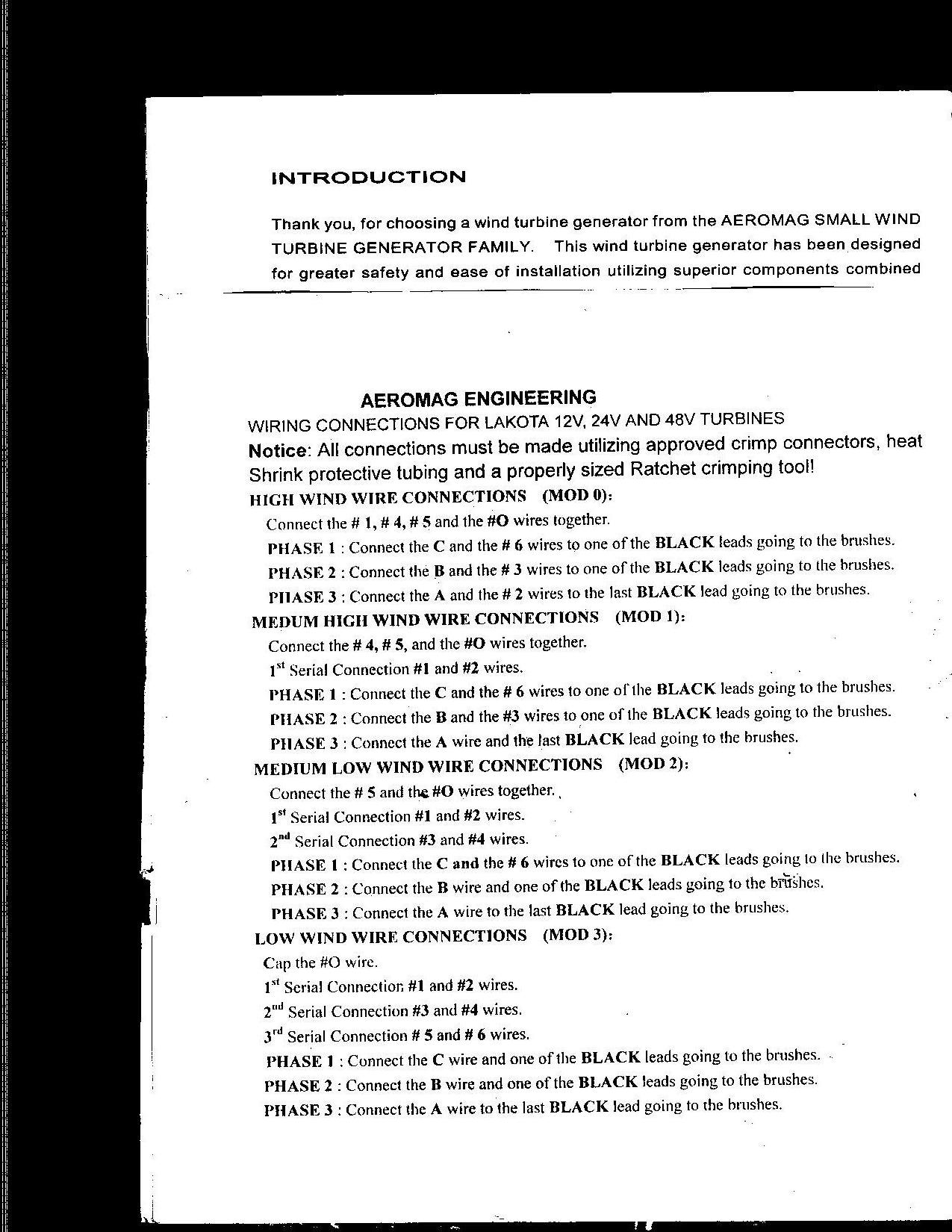 |
||||
Gill Senior Member Joined: 11/11/2006 Location: AustraliaPosts: 669 |
G'day Herb, Thanks for that info. It took me a bit to work out because of the odd numbering. It obviously works in spite the imbalance. I wonder how good that system is and are there any inherent week spots? What's more, how do I apply this to 7 Phase??????????? This pic for those to full of Christmas cheer to work it out. 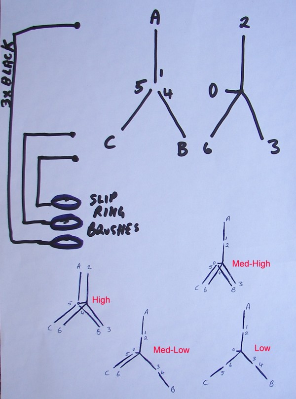 was working fine... til the smoke got out. Cheers Gill _Cairns, FNQ |
||||
| KiwiJohn Guru Joined: 01/12/2005 Location: New ZealandPosts: 691 |
Hmmm, I guess there is nothing actually wrong with adding out of phase windings. In fact it might actually be a very cunning plan, so cunning you could pin a tail on it, so to say. Adding windings that are out of phase would give a voltage increase somewhat less than twice, 33% maybe? So, ummm, maybe: High= 2 Med-High 1.66 Med-Low =1.33 Low=1 I am trying to imagine if 'inbalance' is significant, somehow I dont think so. It looks like a valid technique to me. |
||||
| Gill Senior Member Joined: 11/11/2006 Location: AustraliaPosts: 669 |
Yes John, I am inclined to agree with those figures. What's more with Star/Delta you need 2 x relays for switching and you get 2 configurations. With this one you need 3 relays and get 4 configurations. More gooderer. For anyone with a test rig and keen to do some testing, here's additional circuitry for manual switching between the 4 modes. Not so hard really. Could all be done on one stator. 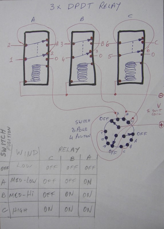 was working fine... til the smoke got out. Cheers Gill _Cairns, FNQ |
||||
| herbnz Senior Member Joined: 18/02/2007 Location: New ZealandPosts: 258 |
Hi It is interesting more I think about it. Initially The output from the rectifiers will be from the phases that have the higest vector sum. But if the configeration not changed then like Glens arrangement the winding/ windings with high ampere turns will current limit,reduce voltage and the other winding will take over heading towards a balance again. I will do the vectors, found my cad prog excellant when I analysed 7 phase to see if you can connect delta. (you can they cancel out ) Herb Ps nice one Gill spotting what they meant by brushes and showing interpretation of manual . |
||||
| Gizmo Admin Group Joined: 05/06/2004 Location: AustraliaPosts: 5182 |
This is interresting. On my staggered set up I have four groups, all different. Each group is a complete 3 phase alternator in its own right, its the different cut in voltage for each group that gives my staggered output. But I needed to have a brigde restifier for each group to stop a early starting group draining back through a late starting group. The Aeromag solution was to have different voltage phases, so only one bridge rectifier was needed. It all makes sense, its OK to have different voltage phases, they all get combined together in the end when under load. So at low speed only one phase is supplying the current, as the speed increases the other phases cut in and supply current also. This opens up a whole new path for re-wiring the F&P. My stagered dual stator works very well, I wish I could give acurate figures, buts its just always making power even in light winds. I think the best way to describe it, there is no sudden cut in as the windmill speeds up. The power curve is flatter from low RPM to high RPM. so let me confirm that, Delta on 7 phase wont work. I always suspected that, but wasnt sure. Glenn The best time to plant a tree was twenty years ago, the second best time is right now. JAQ |
||||
| Gill Senior Member Joined: 11/11/2006 Location: AustraliaPosts: 669 |
Ahhhh. Amazing what a couple of Bundies and a good nights sleep can bring. I can now assert with confidence the system is indeed balanced in all it's configurations in spite it's physical appearance. Like a triangle where a circle can always pass through each point or a three legged table can never rock, any 3 phase configuration will always be in balance. 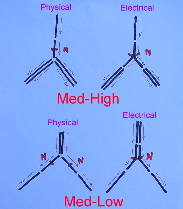
A technique is used on radio antenna where wires are split or combined(G5RV,Zep,Bazooka to name a few)to achieve physical relationships for construction that seem less than ideal yet with respect to their currents they are fine. Using the first Physical sketch, take a razor and split the wire lengthwise from the bottom up to the Neutral mark. Now pull the two legs and apart and you have the true electrical arrangement. See voltages are indeed balanced. I have also drawn the currents as relating to each coil and this confirms the balance. Conversely, for the lower Physical sketch, pull in on the two Neutral points till they touch and you have the end sketch of the true electrical arrangement. You could solder these points together without effecting anything but only in this configuration. I for one will not hesitate using this principal with confidence as soon as circumstances allow. Masthead PICAXE switching of course. Unfortunately, like a seven legged table, 7 phase cannot have a shorter leg and not suffer consequences. I won't waste my time pursuing that unicorn further. was working fine... til the smoke got out. Cheers Gill _Cairns, FNQ |
||||
| herbnz Senior Member Joined: 18/02/2007 Location: New ZealandPosts: 258 |
Glen posted 7 phase side track of mine new topic. Gill interesting your explaination will take a few more bundies here but yes it will operate I am sure note also that the neutral point is floating if it was a load this would make the voltages different in fact it would try to balance currents. Here winding voltage can not change much . Herb |
||||
| Gill Senior Member Joined: 11/11/2006 Location: AustraliaPosts: 669 |
7 Phase Delta. Yes they cancel out when you connect 1,2,3,4,5,6,7 in that order. It appears you did not read my post or use 1,3,5,7,2,4,6. It is that anomaly of 3 that makes everybody think 3 phase Delta is 1,2,3 , it is not per sai. Rotating past 123 in that order you get 1, miss2, then3, miss1, then2. this reads as 1,3,2 but because of the 3 thingy it is seen as the reverse of 123. Assumptions! Assumptions! You cannot just change any two with 7 phase and get the reverse nor any 6 for that matter. What more can I say? was working fine... til the smoke got out. Cheers Gill _Cairns, FNQ |
||||
| The Back Shed's forum code is written, and hosted, in Australia. | © JAQ Software 2026 |
