
|
|
Forum Index : Windmills : 7 phase F&P using hard drive magnets
| Page 1 of 2 |
|||||
| Author | Message | ||||
| spiral Newbie Joined: 06/05/2008 Location: Posts: 12 |
Hello I just wanted to post and tell everyone about the F&P I've been working on, since I have not heard of this being done before. I have rewired my motor to 7 phase 2 pole and used my old hub, but replaced the magnets with hard drive magnets piled 2 high, and placed in the 48 magnet new hub pattern. they stick right onto the laminations on the hub(I have not glued them on yet). These hard drive magnets are far stronger than original F&P magnets. I just left them whole(N&S on each face) and placed them on end onto the laminations, this makes a slight skew, as the magnets are curved. It seems to work great. there is no cogging and I am able to power a 1.5A bulb and a 1.5A fan easily by just turning with my finger. I have yet to permanently place the magnets since I want to do some testing for placement and power output, etc. I must say it took a while to take apart all those old hard drives. |
||||
| Gizmo Admin Group Joined: 05/06/2004 Location: AustraliaPosts: 5182 |
Hi Spiral Well this sounds interesting. As far as I know you the first to try a 7 phase with HD magnets, or any magnets other than the standard ferrite magnets. Well done! Its good to hear there is no cogging with the stronger magnets. Keep us posted. Glenn The best time to plant a tree was twenty years ago, the second best time is right now. JAQ |
||||
Steve9R Regular Member Joined: 24/01/2006 Location: AustraliaPosts: 72 |
can you post some pics ? Steve |
||||
| spiral Newbie Joined: 06/05/2008 Location: Posts: 12 |
I would be happy to post a few pics. Anything in particular you want to see? I will assume the magnet placement on the hub is what you are after. Check back in a day or two. |
||||
| spiral Newbie Joined: 06/05/2008 Location: Posts: 12 |
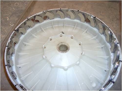
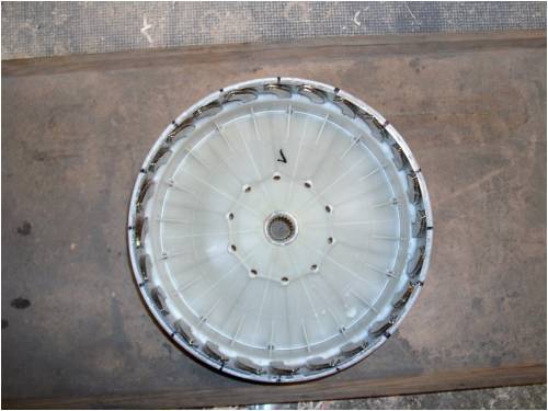
Here are a few images of the magnet hub. I placed the magnets with the hub on the shaft so I could see where to line up the magnets so they were in phase with each stator coil, and used a brass rod to position them. I hooked this up and it spun at about 250 RPM without anything(glue) holding the magnets in place. They didn't move a bit. At this point I need to get a larger ammeter to do a bit more testing. I may have to build a piclog now. By the way thanks for the site and all the info. I love to tinker with DIY energy projects. I felt like I won the lottery when I found a F&P machine here in the states, they are not easy to come by here. |
||||
| Steve9R Regular Member Joined: 24/01/2006 Location: AustraliaPosts: 72 |
cool... what sort of hard drives are they from ? Steve |
||||
| spiral Newbie Joined: 06/05/2008 Location: Posts: 12 |
They are from many different kinds of hard drives. I got double the amount of drives from a computer repair shop, and took them apart. The magnet sizes vary so it is helpful to try and get the same brand, but they tend to be roughly the same sizes. I plan on taking apart more as time goes on so that they are all the same size and thickness. The motor that powers the harddisk is similar to the F&P only very tiny. |
||||
| GWatPE Senior Member Joined: 01/09/2006 Location: AustraliaPosts: 2127 |
Hi spiral, those magnets are from the voice coil actuator, that drives the pickup heads. I believe most are praesodymium alloy. I read once that Japanese companies used this rare earth compound. This alloy tends to be softer and less brittle than the Neodymium Iron Boron alloy. The magnets are still a good find. I use them for fridge magnets... Gordon. become more energy aware |
||||
Gill Senior Member Joined: 11/11/2006 Location: AustraliaPosts: 669 |
G'day spiral, I've just tested some hard drive magnets and found on the flat face that faces the stator, They are not all one magnetic pole. Mine has one pole in the middle with the other at each end. Are yours the same as mine? I suspect so. HDD Magnets 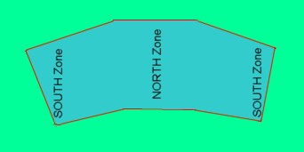
If so this magnetic configuration will not work as both magnetic poles are adjacent any one stator pole pole at the same time. It will have magnetic attraction to the stator laminations but will not cause the flux to flow through the coil and this is what induces the current to flow. I can't think of a way of using these magnets unless they can be cut. I'll leave that for you to explore. I hope you find a way. was working fine... til the smoke got out. Cheers Gill _Cairns, FNQ |
||||
| GWatPE Senior Member Joined: 01/09/2006 Location: AustraliaPosts: 2127 |
Hi spiral, I have tested some magnets from the voice coil actuator of a hard disk drive, that look very similar to the ones you have used and they all have a north / south through the thickness orientation at one and the opposite polarity at the other. The ones I tested had curved inner and outer edges. They were not flatenned like Gills' picture. The ones I have would work. .. .. Gordon. edit.. One thing I have noticed on your layout. The magnets are not a very good shape to suit the F&P rotor. I expect that the output waveform may be a little strange. become more energy aware |
||||
| spiral Newbie Joined: 06/05/2008 Location: Posts: 12 |
Hi again, The magnets I have all have the north/south poles on the same face. They do work. My testing has just begun, but I have set it up at 150 RPM and get 15V unloaded. With a small 12v 1.6A fan hooked up it operated the fan easily, reading 11.6V. I have yet to add more of a load. I had set it up spinning at a higher RPM, around 280, and got a voltage of around 30. I will need a larger ammeter to do more testing. I am curious to see what the waveform looks like as well. I think I can use my multimeter and connect it up to a laptop and check that. I will post when I get to that. The testing end of this is all new to me so I am learning as I go. I wish I had some sort of variable speed motor to drive this. I will have to get one. When I came up with the idea to do this I had planned on cutting the magnets and arranging the poles in a more linear fashion around the hub, but then I read about a company that skewed their stators to help with cogging. I thought, maybe skewing the magnet would also work. Plus the natural curve of the magnet lent itself to this. It was worth a shot, you can imaging my delight when I got it together and lit my first light bulb, by just turning it by hand. At this point I am just happy to play around and am pleased to be able to use my old style hub. I was trying to use an old pot or something to mount the magnets to, but then discovered there were laminations behind the existing magnets on the F&P hub. Voila. |
||||
| Gill Senior Member Joined: 11/11/2006 Location: AustraliaPosts: 669 |
Spiral, That they have "north/south poles on the same face" is not the problem as such, it is where these are located on the face that I see as the problem. I think Gordon says his has the poles at each end. I am surprised as I have several HDD magnet types here and they do not. 
For those considering a similar modification, it may pay to check by sprinkling some iron powder or fine iron filings above the intended magnet and seeing if you get the twin arrangement I have identified. 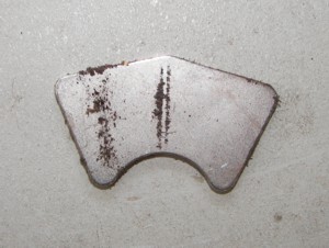
If this happens, better go look for spiral and Gordon's single type like I am. spiral, good to see you are getting some useful voltages out. Look forward to some power figures when you get some to hand. was working fine... til the smoke got out. Cheers Gill _Cairns, FNQ |
||||
| GWatPE Senior Member Joined: 01/09/2006 Location: AustraliaPosts: 2127 |
Hi Gill, I use a needle to find the pole of the magnet. Filings tend to stick to where the field is concentrated. My method is hold the magnet in one hand and the needle in the other. Hold the needle at an end. Move the other end of the needle over the magnet surface of interest. The needle will align to the magnetic field. The hard drive magnet shows a distinct null between the two poles. The needle will jump from pole to pole. The needle tends to centre in the area I have shown on the picture marked N and S 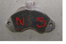
I think you will find that the line the filings make is not a pole. .. .. Gordon. become more energy aware |
||||
| spiral Newbie Joined: 06/05/2008 Location: Posts: 12 |
Hello again I set up a makeshift testing station today, with some adjustable belt configurations, and added some loads to check output. What I had laying around were 3 floodlights that are 12V 18Watt, and 1 fan 12v 1.58A. The F&P spun at 200 RPM and with all three lights hooked up I got 12.25V and 4A. The lights were at full brightness. I then added the fan and with all 4 working together I got 9.5V and 4.5A. The lights were a bit dimmer with this setup, but all 4 were working fine. I don't really know what RPM is an average but 200 seemed like a good place to start. Do you guys have any testing tips that might help beyond this point. I have a charge controller for some solar panels that logs amp hours but I don't know if it can divert the load or if it only shorts it. I would hate to ruin it. I tried to set up my multimeter and hook it up to the computer(It has a program called meterview, that is essentially a scope) and I was able to get it to log voltage, but then my computers battery died and needed recharging, so I didnt get very far. I also dont know how to hook it up to get a proper reading. Do I isolate one of the phases? Perhaps you folks could help with that. All the hard drive magnets I came across have a N/S pole on each face, with the center being the dividing line. I would still like to try to skew the magnets a bit more to eliminate any overlapping of the poles, but they had a natural tendency to position themselves where they are in the photo so there they sit. I do not know what a regular F&P output is so I dont know if this arrangement is better or worse than usual, but I am pleased enough so far. I can charge batteries with that. |
||||
| Tinker Guru Joined: 07/11/2007 Location: AustraliaPosts: 1904 |
Spiral, good to see that you are having fun and also pick up experience as you go. Regarding your HD magnet test results, I hate to mention that you get a lot more power from the original magnets that were in the hub. I seem to recall getting over 200W @ 13.6V and 200RPM with the 7 phase conversion. With regard to variable speed, perhaps you could utilise the multi gear drive of an old pushbike with your motor. I used my lathe but could not run it faster than 200RPM as the V-belt driving the F&P shaft started squealing horribly under the load. Tinker Klaus |
||||
| spiral Newbie Joined: 06/05/2008 Location: Posts: 12 |
Hello Klaus' Thanks for the reference. I would be curious to know what your load was. Was it charging a battery, or did you have a specific load on your F&P. I noticed I got different readings depending on what I had hooked up to it. I also used some old toaster elements and a cooler/warmer. I will try to skew the magnets a bit more to see if the readings change. Is there some standard way of getting readings that I should try, or is what I did normal? |
||||
| Gill Senior Member Joined: 11/11/2006 Location: AustraliaPosts: 669 |
Gordon, From your explanation I'll not be looking for those magnets any more as it seems we are testing the same thing but are coming to different conclusions. We disagree. Such is life. I'll move on. was working fine... til the smoke got out. Cheers Gill _Cairns, FNQ |
||||
| spiral Newbie Joined: 06/05/2008 Location: Posts: 12 |
I did a little more testing, and got slightly better output, but not much. With the three lights hooked up I got 16V and 5A at 200RPM, so about 80watts. It sounds like this is around half what normal output is. Not what I was wishing for but it does work. I tried some different magnet configurations but the one in the picture gives the best output so far. I did notice that my air gap is quite large compared to the factory hub, and will try to either add another magnet or build out the laminations with another layer. |
||||
| GWatPE Senior Member Joined: 01/09/2006 Location: AustraliaPosts: 2127 |
Hi Gill, This may be purely accademic now as it would seem that the power output from this modification is less than the original design. The increased air gap and the non ideal pole shape would probably account for the reduced output. I had tried using the hard drive magnets in an early axial flux design, but this did not work out either. BTW did a needle test on your magnets indicate a pole along the line that the filings made? .. .. Gordon. become more energy aware |
||||
| spiral Newbie Joined: 06/05/2008 Location: Posts: 12 |
I sped this up a little. At 300Rpm it puts out 110watts at 16.5V. Frankly, I am happy with that. It is as much as my solar panel I have set up. I feel like I have only just started to try this out. I am not ready to trash on it yet. There are plenty of fairly easy ways to try to improve it,as it is still in rough draft stage. In fact I have only tested it for perhaps two hours. When I started I was faced with wiring it in 3 or 7 phase. Since I didn't have the newer hub but still wanted to wire it up for 7, this plan let me move forward. I would be interested in what someone else's output is for 7 phase. Klaus said 200watts at 200 RPM. Is this the normal output? It seems to me I read people got 150watts at 300RPM. Perhaps someone else has data. Also if anyone has a minute to tell me how they get their data I would appreciate it. This is the first alternator I have ever tested. |
||||
| Page 1 of 2 |
|||||
| The Back Shed's forum code is written, and hosted, in Australia. | © JAQ Software 2026 |
